
Related Manuals for Carrier TRANSICOLD 69UG15 Series


Summary of Contents for Carrier TRANSICOLD 69UG15 Series
- Page 1 Diesel Generator Set OPERATION AND SERVICE 69UG15 Generator Set Units: PID UG1400 Series PID UG1500 Series PID UG1600 Series T−343 Rev B...
- Page 2 OPERATION AND SERVICE MANUAL DIESEL DRIVEN GENERATOR SET MODEL 69UG15...
- Page 3 TABLE OF CONTENTS PARAGRAPH NUMBER Page SAFETY SUMMARY ..............Safety−i GENERAL SAFETY NOTICES .
-
Page 4: Table Of Contents
TABLE OF CONTENTS − Continued PARAGRAPH NUMBER Page TROUBLESHOOTING ............... . . 3−1 DIESEL ENGINE . - Page 5 LIST OF ILLUSTRATIONS FIGURE NUMBER Page Figure 1-1 Generator Set ..............1−3 Figure 1-2 Generator Set −...
- Page 6 SAFETY SUMMARY GENERAL SAFETY NOTICES The following general safety notices supplement the specific warnings and cautions appearing elsewhere in this manual. They are recommended precautions that must be understood and applied during operation and maintenance of the equipment covered herein. The general safety notices are presented in the following three sections labeled: First Aid, Operating Precautions and Maintenance Precautions.
- Page 7 SPECIFIC WARNING AND CAUTION STATEMENTS The statements that follow are applicable to the generator set and appear elsewhere in this manual. These recom- mended precautions must be understood and applied during operation and maintenance of the equipment covered herein. WARNING CAUTION Never pour cold water into a hot engine.
- Page 8 DESCRIPTION 1.1 INTRODUCTION pressure, high water temperature, overspeed, and other overcrank conditions. The Carrier Transicold model 69UG15 under−mounted Carrier Transicold’s Ecodriven dual speed option diesel−driven generator sets provide electrical power provides an energy saving alternative to the practice of for all−electric refrigeration units.
-
Page 9: Table 1-1 Model Chart
Table 1-1 Model Chart Electrical Wiring Unit Control Schematic and Model Receptacle Box Mounting Box, 460 Volt Diagram Figures 1400 Series, Single Speed UG1450 5-10, 5-11, 5-12 Standard w/Circuit Breaker Standard (Figure 2-1) UG1451 5-1, 5-2, 5-3 Standard w/Circuit Breaker Standard 69UG15−050S−05 UG1452... -
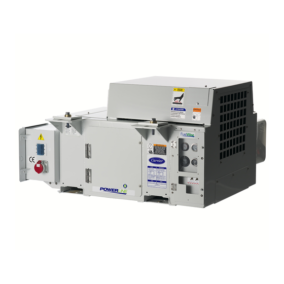
Page 10: Figure 1-1 Generator Set
460 VOLT 1. Mechanical Fuel Pump 11. Air Cleaner 2. Injector Pump 12. Generator Shockmount 3. Engine Speed Sensor 13. Receptacle Box 4. Poly V−Belt 14. Receptacle 5. Radiator 15. Circuit Breaker 6. Controls (See Figure 1-9) 16. Air Filter Indicator (if equipped) 7. -
Page 11: Figure 1-2 Generator Set − Top View (Top Frame Members Removed For Clarity)
1. Fuel Tank 8. Fuel Heater (If Equipped) 2. Exhaust Muffler 9. Fuel Filter 3. Solid State Battery Charger 10.Coolant Overflow Bottle 4. Low Coolant Sensor (If Equipped) 11.Alternating Current Generator 5. Water Temperature Sensor 12.AC Generator Connection Box Access 6. -
Page 12: Figure 1-3 Electronic Governor Module
1.3 ENGINE The engine is a vertical, in−line four cylinder diesel Injector engine, which is direct−connected to the alternating Nozzles current generator. Information on the major engine systems is provided in the following subparagraphs. 1.3.1 Electronic Governor Module The electronic governor module (EG) is a solid state Fuel control module preprogrammed for 1800 RPM high Filter... -
Page 13: Figure 1-6 A−C Generator Circuit Diagram
1.4 ENGINE SCREW THREADS 1.5.2 Alternating Current Generator Diagram Figure 1-6 shows the internal schematic diagram of the All threads used on the engine are metric except for the generator, exciter, and rectifier unit. The generator is a oil drain plug, which is American Standard Pipe Thread three−phase unit, the exciter stator and exciter rotor (NPT). - Page 14 1.7 OPERATING CONTROLS & INSTRUMENTS 2. Total Time Meter (TT) The total time meter (see Figure 1-7, Figure 1-8, 1.7.1 Introduction Figure 1-9) calculates the total hours and provides an Components required for monitoring and controlling the accurate readout of accumulated engine running time. unit are located in the control box, on the control panel This data can be used to establish the proper periodic (see Figure 1-1, item 6) and on the receptacle box (see...
-
Page 15: Figure 1-7 Standard Control Panel And Box With Dual Speed Option
CONTROL CONTROL PANEL 1. Total Time Meter 9. Ground Studs 2. Water Temperature Gauge 10. Circuit Breaker (CB2) 3. Oil Pressure Gauge 11. Circuit Breaker (CB3) 4. Ammeter 12. Intake Heater Relay 5. Intake Heater Switch 13. Safety Relay 6. Ignition Switch 14. -
Page 16: Figure 1-9 Auto Restart Control Box And Panel
CONTROL CONTROL PANEL 1. Total Time Meter 9. Battery Charger Fuse or Circuit Breaker (CB5) 2. Engine Start Alarm (Buzzer) 10. Ground Studs 3. Water Temperature Gauge 11. Circuit Breaker (CB2) 4. Auto Restart Module 12. Starter Relay (SR) 5. Oil Pressure Gauge 13. -
Page 17: Table 1-3 Auto Restart Sequencing
Table 1-3 Auto Restart Sequencing *Engine crank and rest is repeated three times each series unless the engine starts. Intake Engine Engine Heater Series Fuel Crank Rest Attempt Energized Solenoid Engine Status Duration Duration Number Engaged (Seconds) (Seconds) Seconds If the engine starts: a. - Page 18 Table 1-3 Auto Restart Sequencing (Continued) Intake Engine Engine Heater Series Fuel Crank Rest Attempt Energized Solenoid Engine Status Duration Duration Number Engaged (Seconds) (Seconds) Seconds If the engine starts: a. Run sequence begins. If the engine fails to start: a.
-
Page 19: Table 1-4 Safety Devices
1.8 SAFETY DEVICES In units with auto restart, the engine, engine control devices, and engine monitoring devices are protected by the auto restart module, low coolant sensor (if Safety devices, such as circuit breakers, fuses, and equipped), circuit breaker, low oil pressure switch, and safety switches, protect system components from high water temperature switch. - Page 20 1.9 UNIT SPECIFICATIONS Nominal Tank Sizes Fill Capacity Draw Capacity 52 gallons 50 gallons* 50 Gallon Steel (256 liters) (246 liters) 52 gallons 50 gallons* 50 Gallon Aluminum (256 liters) (246 liters) a. Fuel Tanks 67.5 gallons 65 gallons* 65 Gallon Steel (197 liters) (189 liters) 85 gallons...
- Page 21 1.10 ENGINE DATA (Continued) Amperage − 42 amps at 12 VDC i. Intake Heater Resistance (cold) − Approx. 0.3 ohms 27 HP @ 1800 RPM at 3000 feet above sea level. j. Horsepower 32 HP @ 1800 RPM at sea level. 6 U.S.
-
Page 22: Figure 2-1 Generator Set Mounting − Standard Mount
SECTION 2 OPERATION 2.1 GENERATOR SET INSTALLATION b. Quick Mount The generator set is mounted under the center of the 1. Loosen mounting bolts (see Figure 2-2) sufficient trailer chassis and is easily handled with a fork lift truck to bring clamp to open position. To orient in open capable of handling 2,000 pounds. -
Page 23: Figure 2-2 Generator Set Mounting - Quick Mount
CONTAINER FLOOR CROSS I-BEAMS REAR OF CHASSIS FORK LIFT POCKET ROADSIDE VIEW VIEW A - A Angle Assembly, Clamp Washer, Spherical, Belleville Washer, Spherical, Male Roll Pin Washer, Spherical, Female Nut, Hex, 3/4-10 Bolt Frame Assembly Figure 2-2 Generator Set Mounting - Quick Mount 2.2 GENERATOR SET REMOVAL b. - Page 24 2.3 STARTING AND STOPPING INSTRUCTIONS WARNING 2.3.1 Pre-Start Inspection Under no circumstances should ether or a. Check engine lubrication and fuel filters, oil lines, and any other unauthorized starting aids be connections for leaks. If required, tighten connec- tions and/or replace gaskets. used in conjunction with the air intake heater.
- Page 25 2.3.3 Post-Start Inspection Once the engine has started, the intake heater (IH) will remain energized for 3 minutes. a. Allow the Genset unit to run for at least 2 minutes. The ignition switch (IGN) will be released. The intake b. Turn on CB-1 for 460 volt units. heater switch (HS) will be held for 5 seconds, then c.
-
Page 26: Troubleshooting
SECTION 3 TROUBLESHOOTING REMEDY/ CONDITION POSSIBLE CAUSE REFERENCE SECTION 3.1 DIESEL ENGINE 3.1.1 Engine Will Not Start Battery insufficiently charged Charge Battery terminal post or battery defective Check Electrical connections at starter are bad Correct Starter motor will not crank or low Starter motor malfunctions See 3.1.4 cranking speed... -
Page 27: Engine Will Not Shut Off
REMEDY/ REFERENCE CONDITION POSSIBLE CAUSE SECTION 3.1.3 Engine Will Not Shut Off Loose ground connection Clean/Tighten Engine will not shut off Improperly seated fuel solenoid Correct 3.1.4 Starter Motor Malfunction Battery insufficiently charged Charge Battery cable connections loose or oxidized Check/Replace Battery cables defective Check/Replace... -
Page 28: Miscellaneous Engine Troubleshooting
REMEDY/ REFERENCE CONDITION POSSIBLE CAUSE SECTION 3.1.6 Miscellaneous Engine Troubleshooting Restriction in air cleaner Section 4.4.12 Air in fuel system Section 4.4.1 Air vent restricted Clean Restricted fuel lines Engine Manual Loss of power Fuel injection pump is bad Engine Manual Injector(s) bad or incorrect type used Engine Manual Incorrect fuel injection pump timing... -
Page 29: Alternating Current Generator
REMEDY/ REFERENCE CONDITION POSSIBLE CAUSE SECTION 3.2 BATTERY CHARGER (SOLID STATE) (CONTINUED) Open input circuit breaker Reset Charger is not receiving AC input Using a voltme- ter, confirm charger is receiv- ing correct (230v) AC voltage. If not, check input Charger does not charge connections. - Page 30 REMEDY/ REFERENCE CONDITION POSSIBLE CAUSE SECTION 3.3 ALTERNATING CURRENT GENERATOR (CONTINUED) Generator overloaded Check Clogged ventilating screens Clean High temperature surrounding generator Section 4.4.5 Overheating Insufficient air circulation Section 4.5.1 Unbalanced load Balance Dry bearing Section 4.5.1/ 4.5.3 Bad bearing Section 4.5.1/ 4.5.3 Rotor scrubbing on stator...
- Page 31 REMEDY/ REFERENCE CONDITION POSSIBLE CAUSE SECTION 3.4 AUTO RE-START OPTION (CONTINUED) Engine starts, but shuts down from Electronic Governor Module (EG) is bad Replace over speed Electronic Governor Module (EG) is bad Replace Engine cranks, but will not start See 3.1.1 See 3.1.1 Engine starts, but shuts down on See 3.1.2...
-
Page 32: Service And Preventative Maintenance
SECTION 4 SERVICE AND PREVENTATIVE MAINTENANCE 4.1 INTRODUCTION c. Turn filter (item 3) counter-clockwise and remove. Check and clean. This section covers service for the generator set and d. To install, reverse steps 1 through 3. general engine service. Refer to the Kubota engine workshop manual, Section 1.1, for additional engine servicing. -
Page 33: Lube Oil Filter
d. Run engine 6 to 12 hours and drain system while CAUTION warm. Rinse system three times after it has cooled down. Refill system with water. Never open the radiator cap when the cool- CAUTION ant is hot. Use only ethylene glycol, anti-freeze (with inhibitors) in system. -
Page 34: Servicing Poly V-Belt
4.4.11 Servicing Poly V-belt a. Air Filter Indicator The air filter indicator, used with the dry element filter, is mounted on the unit frame and connected to the engine WARNING air intake. Its function is to indicate when the air cleaner dry element needs to be replaced. -
Page 35: Engine Crankcase Breather
CAUTION Do not underfill or overfill the oil bath cups. Overfilling cups causes loss of capacity; underfilling cups causes lack of filtering efficiency. 1. Screw 4. Breather Valve 2. Breather Cover 5. Breather Tube 3. Bleed Hole Figure 4-5 Engine Crankcase Breather 4.4.14 Intake Heater Test a. -
Page 36: Intake Heater Switch
To repair a rotor, the GENERATOR special tooling and technique of the factory are 4.5.1 Preventative Maintenance and necessary and essential. Should a failure occur, Carrier Operating Precautions Transicold should be notified immediately and steps will be taken to return the generator for service. -
Page 37: Bearing Replacement
Coat mating surface of bearing cover flange with 1. Remove the bearing cover by removing the four bolts anti-corrosion compound (Tef-Gel, Carrier Part (see Figure 4-8). Both the bearing and diode assem- Number 02-00083-00). -
Page 38: Generator Removal And Installation
4.5.4 Generator Removal and Installation CAUTION a. Removing the Generator The rotor should not be pulled out from the 1. Remove covers and ground wire from frame of alternator more than 0.75 inches. Damage generator set. to the bearing and windings may result. 2. -
Page 39: Check And Replace Isolators/Shockmounts
4.6.2 Check and Replace Isolators/Shockmounts c. Generator Shockmount Replacement a. Replacement Criteria 1. Use the two lift eyes to lift and support the engine. CAUTION 2. Remove shockmount hardware. 3. Raise the generator just enough to remove the Continued operation with failed shock- shockmounts (Figure 4-11 item 7). -
Page 40: Unidrive Torque Requirements
4.7 UNIDRIVE TORQUE REQUIREMENTS assembly are provided in Figure 4-12. Extensive damage may occur if the proper hardware is NOTES not used and/or proper procedures are not followed SST is an abbreviation for 300 Series Corrosion when working with the unidrive assembly. Periodic Resistant Steel. -
Page 41: Table 4-1 Preventative Maintenance Actions And Schedule
Table 4-1 Preventative Maintenance Actions and Schedule Extended Standard Service Service Perform Interval Units Interval Reference Units* Description of Procedure Paragraph Pre-Trip Every Annually Annually Inspection 1000 or Every or Every Hours 3000 H 3000 ours Hours For Pre-Trip inspection, perform items 1 through 15; for “After Start-up” checks, perform items 32 through 36. 1. - Page 42 Table 4-1 Preventative Maintenance Actions and Schedule (Continued) Extended Standard Service Service Perform Interval Units Interval Units Reference Description of Procedure Pre-Trip Paragraph Every Annually Annually Inspection 1000 or Every or Every Hours 3000 Hours 3000 Hours See Engine 20.Check water pump bearing end play Manual 21.Change fuel filter 4.4.3...
-
Page 43: Figure 5-1 Schematic Diagram - Legend
SECTION 5 SCHEMATICS 5.1 INTRODUCTION This section contains the 12-volt DC control circuit schematics and the 460 volt alternating current generator schematics. To identify the schematics applicable to your PID number refer to Table 1-1. Based On Drawing 62-11411-00 Rev- Figure 5-1 Schematic Diagram - Legend (Applies to Figures 5-2 thru 5-3) T-343... - Page 44 Based On Drawing 62-11411-00 Rev- Figure 5-2 Schematic Diagram (For Applicability, Refer to Table 1-1) T-343 5−2...
-
Page 45: Figure 5-3 Schematic Diagram 460 Volt Alternating Current Generator
NOTE: WHEN PE IS NOT FITTED, OUTPUT GROUND WIRES ARE CONNECTED DIRECTLY AT GENERATOR TERMI- NAL STRIP TERMINAL T10. Based On Drawing 62-11411-00 Rev- Figure 5-3 Schematic Diagram 460 Volt Alternating Current Generator (For Applicability, Refer to Table 1-1) T-343 5−3... -
Page 46: Figure 5-4 Schematic Diagram - Legend
Based On Drawing 62-11413-00 Rev A Figure 5-4 Schematic Diagram - Legend (Applies to Figures 5-5 thru 5-6) T-343 5−4... - Page 47 Based On Drawing 62-11413-00 Rev A Figure 5-5 Schematic Diagram (For Applicability, Refer to Table 1-1) T-343 5−5...
-
Page 48: Figure 5-6 Schematic Diagram 460 Volt Alternating Current Generator
Based On Drawing 62-11413-00 Rev A Figure 5-6 Schematic Diagram 460 Volt Alternating Current Generator (For Applicability, Refer to Table 1-1) T-343 5−6... -
Page 49: Figure 5-7 Schematic Diagram - Legend
Based On Drawing 62-11466-00 Rev B Figure 5-7 Schematic Diagram - Legend (Applies to Figures 5-8 thru 5-9) T-343 5−7... - Page 50 Based On Drawing 62-11466-00 Rev B Figure 5-8 Schematic Diagram (For Applicability, Refer to Table 1-1) T-343 5−8...
-
Page 51: Figure 5-9 Schematic Diagram 460 Volt Alternating Current Generator
NOTE: WHEN PE IS NOT FITTED, OUTPUT GROUND WIRES ARE CONNECTED DIRECTLY GENERATOR TERMINAL STRIP TERMINAL T10. Based On Drawings 62-11466-00 Rev- B Figure 5-9 Schematic Diagram 460 Volt Alternating Current Generator (For Applicability, Refer to Table 1-1) T-343 5−9... -
Page 52: Figure 5-10 Schematic Diagram - Legend
Based On Drawing 62-11438-00 Rev D Figure 5-10 Schematic Diagram - Legend (Applies to Figures 5-11 thru 5-12) T-343 5−10... - Page 53 Based On Drawing 62-11438-00 Rev D Figure 5-11 Schematic Diagram (For Applicability, Refer to Table 1-1) T-343 5−11...
-
Page 54: Figure 5-12 Schematic Diagram 460 Volt Alternating Current Generator
NOTE: WHEN PE IS NOT FITTED, OUTPUT GROUND WIRES ARE CONNECTED DIRECTLY GENERATOR TERMINAL STRIP TERMINAL T10. Based On Drawing 62-11438 Rev D Figure 5-12 Schematic Diagram 460 Volt Alternating Current Generator (For Applicability, Refer to Table 1-1) T-343 5−12... -
Page 55: Figure 5-13 Schematic Diagram - Legend
Based On Drawing 62-11441-00 Rev D Figure 5-13 Schematic Diagram - Legend (Applies to Figures 5-14 thru 5-15) T-343 5−13... - Page 56 Based On Drawing 62-11441-00 Rev D Figure 5-14 Schematic Diagram (For Applicability, Refer to Table 1-1) T-343 5−14...
-
Page 57: Figure 5-15 Schematic Diagram 460 Volt Alternating Current Generator
NOTE: WHEN PE IS NOT FITTED, OUTPUT GROUND WIRES ARE CONNECTED DIRECTLY GENERATOR TERMINAL STRIP TERMINAL T10. Based On Drawing 62-11441 Rev D Figure 5-15 Schematic Diagram 460 Volt Alternating Current Generator (For Applicability, Refer to Table 1-1) T-343 5−15... - Page 58 INDEX AC Generator Description, 1−6 First Aid, Safety−i Air Cleaner, Dry Element Service, 4−3 Fuel Filter, 4−1 Air Cleaner, Oil Bath Service, 4−3 Fuel Pump Filter Service, 4−1 Air Filter Indicator, 4−3 Fuel System, 1−5 Alternating Current Generator Diagram, 1−6 Ammeter, 1−7 Auto Restart Module, 1−7 Auto Restart Preset Values, 1−9...
- Page 59 INDEX (Continued) Safety Devices, 1−12 Maintenance Precautions, Safety−i Safety Notices, Safety−i Manual Switches, 1−7 Safety Summary, Safety−i Meters, 1−7 Schematics, 5−1 Model Chart, 1−2 SEQUENCE OF OPERATION, 2−4 Starting Instructions, 2−3 Stopping Instructions, 2−3 Operating Controls and Instruments, 1−7 Operating Precautions, Safety−i Timers, 1−7 Torque Requirements, 4−9 Total Time Meter, 1−7...
- Page 60 Carrier Transicold Division, Carrier Corporation Container Products Group P.O. Box 4805 Syracuse, N.Y. 13221 U.S A www.carrier.transicold.com A member of the United Technologies Corporation family. Stock symbol UTX ©2010 Carrier Corporation D Printed in U. S. A. 11/11...
Need help?
Do you have a question about the TRANSICOLD 69UG15 Series and is the answer not in the manual?
Questions and answers