Table of Contents
Advertisement
Quick Links
Advertisement
Table of Contents

Subscribe to Our Youtube Channel
Related Manuals for GEZE MBZ300


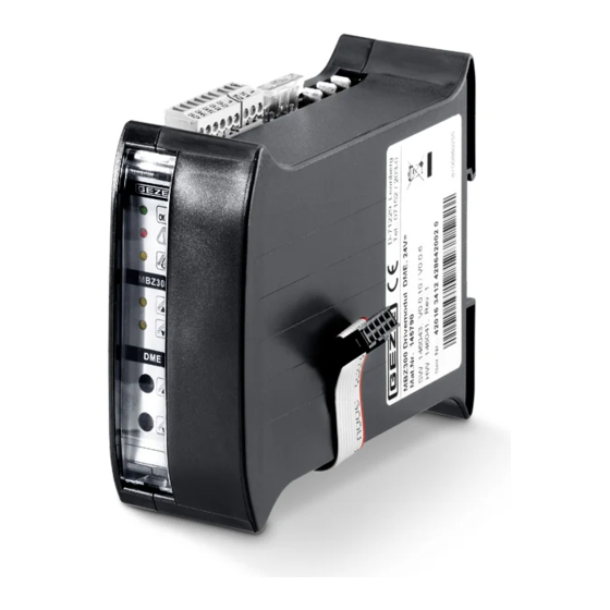
Summary of Contents for GEZE MBZ300
- Page 1 230V 230V 230V 230V 230V 230V MBZ300 MBZ300 MBZ300 MBZ300 MBZ300 MBZ300 MBZ300 MBZ300 MBZ300 MBZ300 MBZ300 MBZ300 MBZ300 MBZ300 MBZ300 Reset Reset MBZ300 EN Installation instructions Emergency power supply control unit 137265-04...
-
Page 2: Table Of Contents
Standard control units ....................................7 Object-specifically pre-configured control panels ..........................8 Installation ..................................8 Control cabinet ventilation ...................................8 Equipment and configuration of the MBZ300 control panel ......................9 Connection of the MBZ300 control panel .............................13 Installing the CAN module ..................................19 Commissioning ..............................21 Operation ................................21 General mode of operation .................................. -
Page 3: Symbols And Illustrations
Act”, compliance with the information contained in this brochure (product information and intended use, misuse, product performance, product maintenance, obligations to provide information and instructions) must be ensured. Failure to comply releases the manufacturer from his statutory liability. GEZE makes no guarantee for combinations with third-party devices. - Page 4 Secure workplace against unauthorised entry. Ensure that mounting, commissioning and maintenance are only carried out by qualified personnel author- ised by GEZE. If unauthorised changes are made to the system, GEZE cannot be made liable in any way what- soever for any resulting damages.
-
Page 5: What To Do In The Event Of Fire
The rooms are ventilated with the emergency power control unit and smoke is automatically removed in the event of fire. The MBZ300 emergency power control unit fulfils sound engineering practice and conforms to the applicable safety regulations. The system is exclusively intended to be used in dry rooms. -
Page 6: Properties
à Thanks to the possibilities of the software configuration and the extensive area of application of the modules, special installations in the control panel are hardly necessary for special applications. Components of the MBZ300 control panel 2.4. 1 Power supply (depending on the version) à... -
Page 7: Standard Control Units
Modules à Power module PM: à 24 A or 10 A (depending on switching power supply unit), with MBZ300 N8 max. 8 A possible à Power module extension PME: à 24 A or 10 A additionally (depending on switching power supply unit) for the 2nd or 3rd switching power supply unit à... -
Page 8: Object-Specifically Pre-Configured Control Panels
Later complaints will not be accepted. à The MBZ300 emergency power control unit must be installed in a location protected from heat. Have someone hold the control cabinet and the MBZ300 emergency power control unit during screwing. -
Page 9: Equipment And Configuration Of The Mbz300 Control Panel
MBZ300 Installation Equipment and configuration of the MBZ300 control panel Overview of the modules and components à Power module PM à Power module extension PME à Control module CM à Sensor module SM à Drive module DM / DME à Weather module WM à... - Page 10 The capacity required must be calculated in the case of deviating combinations. Drive modules DM for ventilator groups One drive module DM makes max. 10 A (with MBZ300 N8 max. 8 A) possible for the connection of a ventilator group. Calculation examples:...
- Page 11 MBZ300 Installation 3.2.2 Space required for the modules and components on the top-hat rail (width) Module à Control module CM, sensor module SM, relay module ERM, , DME drive module DM, weather module WM à approx. 23 mm à Power module PM, power module extension PME, DME à...
- Page 12 Installation MBZ300 3.2.4 Layout of the modules on the top-hat rail It is imperative that the module layout on the top-hat rail is observed. Place the modules on the top-hat rail in the following order directly next to each other (from left to right): à...
-
Page 13: Connection Of The Mbz300 Control Panel
à 1 power module PM with 1 switching power supply unit 10 A or 24 A (with MBZ300 N8 max. 8 A) à 1 power module PM with 1 power module extension PME and 2 switching power supply units 10 A or 24 A à... - Page 14 Installation MBZ300 Connection with two switching power supply units Safety fuse Safety fuse 3 2 1 33 32 1 52 51 1 Operating display (green) Operating display (green) 24 A Status display (green) Fault display (yellow) Fault display (yellow) Alarm (EMERGENCY OPEN) display (red)
- Page 15 MBZ300 Installation Connection with three switching power supply units Safety fuse Safety fuse 3 2 1 33 32 1 52 51 1 Operating display (green) Operating display (green) 24 A Status display (green) Fault display (yellow) Fault display (yellow) Alarm (EMERGENCY OPEN) display (red)
- Page 16 Installation MBZ300 3.3.2 Connection of the internal BUS connection The BUS connections of the modules for the ribbon cable are located on the bottom (only connection PME to PM on the module top). The modules can be connected to each other irrespective of their function in the system (digital BUS system).
- Page 17 MBZ300 Installation 3.3.3 Connection and installation of the batteries Batteries that have not been connected properly can lead to property damage. Ensure correct polarity when connecting the batteries. Connecting cable + (red) Connecting cable – (blue) Ring cable lug with cable...
- Page 18 Installation MBZ300 3.3.5 Connecting external components Ensure that the electrical installation is carried out in accordance with the applicable regulations and guidelines. For low voltages use only cables without protective conductor. Power module PM Control module CM/Sensor module SM Status contact...
-
Page 19: Installing The Can Module
The system must be configured for this application using the system software. With the MBZ300 N8, the CAN module can only be used for the minimum configuration (1×PM, 1×CM, 1×DM). The CAN module is used for connecting several control panels to one control and triggering unit via CAN-bus. - Page 20 Installation MBZ300 Setting the jumper Insert the jumper (terminator) First control panel Control panel(s) Last control panel in the first and last control pan- With jumper Without jumper With jumper els linked via the CAN-bus. Connection All the control panels in between internal bus must not have a jumper.
-
Page 21: Commissioning
Automatic opening and closing (e.g. wind-rain control) overrides manual activation. Ventilation mode The service technician can set parameters for several functions using the MBZ300 configuration software. Opening and closing windows The windows are divided into ventilation groups. Each ventilator group has one or more vent switches which you can use to open and close the windows of the ventilator group together. -
Page 22: Alarm Mode
Operation MBZ300 Opening width restriction The service technician can specify a time-controlled opening width limitation of the windows separately for each drive module. When the drives receive an open-signal from the vent switch, they stop after the prescribed open- ing time. Further opening of the window is only possible after the close-button has been pressed. - Page 23 MBZ300 Operation Completely resetting the system The method for resetting the RWA emergency power supply control unit depends on the cause of the alarm. By an RWA button: Reset the RWA button. By a smoke detector or a heat detector: Reset the smoke detector line and RWA button.
-
Page 24: Power Failure And Fault
à Change fuse if necessary. à Inform a specialist authorised by GEZE in the event of a fault despite intact power supply. Fault Work in the control cabinet is required in case of a fault with a yellow illuminated fault LED. -
Page 25: Module Description
MBZ300 Module description Module description 6. 1 Power module PM Functions: à Monitoring of the mains power supply 230V à Checking of the battery charge voltage 230V à Switching over to battery operation in case of power failure à Connection for sensor used to monitor the battery temperature à... - Page 26 Module description MBZ300 Connections for power module PM System voltage (battery-buffered) Power supply voltage Safety fuse 25 A Connection with PME 1 Operating display (green) Status display (green) Fault display (yellow) blue Sensor for battery temperature To the CM blue...
-
Page 27: Power Module Extension Pme
MBZ300 Module description Power module extension PME Functions: à Monitoring of the mains power supply in case of more than one switching power supply unit 230V à Switching over to battery operation in case of power failure 230V à VdS tested... -
Page 28: Control Module Cm
Module description MBZ300 Control module CM Functions: à Monitoring of three fire alarm lines for triggering and faults à Processing of the signals of vent switches à Connections for external LED displays (operation, fault, alarm and “Window opening”) à Basic equipment of the control panel (direct connec-... - Page 29 MBZ300 Module description Symbol Status Mode of operation/fault yellow, 3 x flash CAN participant missing green, steady light External display “Open window” on All the windows in the fire section RWA button closed yellow, steady light At least 1 ventilator group in the fire...
- Page 30 Module description MBZ300 Connections for control module CM 1st smoke detector Last smoke detector Last RWA button FT4 max. 10 RWA buttons Leave terminal resistors 22 k in line in the last in the series or set DIP switch to ON...
-
Page 31: Sensor Module Sm
MBZ300 Module description Sensor module SM Functions: à Monitoring of three fire alarm lines for triggering and faults à Processing of the signals of vent switches à Connections for external LED display (operation, fault, alarm and “Window opening”) à Use only possible if there is a control module CM MBZ300 à... - Page 32 Module description MBZ300 Connections for sensor module SM Last RWA button FT4 1st smoke detector Last smoke detector max. 10 RWA buttons Leave terminal resistors 22 k in line in the last in the series or set DIP switch to ON...
-
Page 33: Drive Module Dm / Dme
Drive module DM / DME Functions: à Connection for electromotive drives up to max. 10 A/ DME 20 A (with MBZ300 N8 max. 8 A) à Monitoring of the drive power through fail-safe (for fault, short-circuit, interruption) à Processing of the signals of vent switches (if required... - Page 34 The motor supply line is monitored with a third wire with a diode/resistance combination at the last motor in every group. Alternatively, use the GEZE cable end module LED (166090). Line monitoring may not be replaced by a bridge to GND.
- Page 35 à The detector relays must be configured to “Alarm” and assigned to individual fire sections. With the MBZ300 N8 the alarm relay is already pre-wired for 1 alarm group for the signal cable S. Series terminals for connections 1,2,3,S are installed.
- Page 36 Motor (Calculate cable 24 V DC cross-section) max. 10 mm² Series terminal (Mat.-Nr. 150328) *) Alternative: Use GEZE cable end module LEM ID no. 166090 3 WH 2 BK 1 BK FKSE 37 36 35 33 32 1 52 51 1 24 VDC max.
-
Page 37: Weather Module Wm
MBZ300 Module description Weather module WM Functions: à Connections for 1 wind and rain sensor each à Wind direction sensor for wind-dependent opening and closing in case of fire à Processing of the signals of external ventilation control units à Connections for external signal transfer... - Page 38 Module description MBZ300 Connection of a wind and rain sensor set (mat. no. 140229) to weather module WM GC 401 RS GC 402 WVS GC 401 RS GC 402 WVS Rain sensor 24 V Wind sensor Rain sensor 24 V...
- Page 39 MBZ300 Module description Required sensors: à Wind direction sensor GC 403 WDS (mat. no. 140228) à Wind and rain sensor set GC 401 RS and GC 402 WVS (mat. no. 140229) Connection of rain/wind control (mat. no. 091529) “Wind” input must be configured to switching contact setting.
-
Page 40: Relay Module Erm
Module description MBZ300 Relay module ERM The relay module ERM must be configured with the MBZ 300 software. 6.7. 1 Functions à 6 configurable relay outputs à Notification of error and operating statuses MBZ300 Operation (green) Fault (yellow) Display Symbol... -
Page 41: Overview Of The Displays
MBZ300 Overview of the displays Overview of the displays WARNING! Danger to life in case of malfunctions during a fire! The system and its display elements must function correctly. Eliminate all faults immediately. Power module PM Power module extension PME... -
Page 42: Module Configuration
Module configuration MBZ300 Alarm triggering / EMERGENCY OPEN Display element/symbol Display red (on modules CM, SM and DM of the corresponding fire section) red; indicates which drive module DM the smoke and heat extraction units are opened for EMERGENCY CLOSE (closing of the smoke and heat extraction units) is possible with the RWA button. Smoke detectors have to be reset using the Reset switch on the control or sensor module. -
Page 43: Maintenance
(0.1 s). cy power control unit checked by a qualified electrician. Change fuse if necessary. Inform a specialist authorised by GEZE in the event of a fault despite intact power supply. Pressing the vent switch does not Power failure or other Check whether the fault LED on the RWA button move the windows. -
Page 44: Storage
Please dispose of batteries at a municipal collection point or in store. Batteries obtained from us can be returned to us by mail. The address is: GEZE GmbH, Incoming Goods, Reinhold-Vöster-Str. 21-29, 71229 Leonberg/Germany. -
Page 45: Technical Data
Nominal capacity Version-specific (see information plate) Current output switching power supply unit 10 A (short- 10 A (30% duty cycle), with MBZ300 N8 8 A term operation) Current output switching power supply unit 24 A (short- 24 A (30% duty cycle)) -
Page 46: 13. 1 Safety Fuses
Technical data MBZ300 13. 1 Safety fuses Overview of the modules and fuses (each on the top of the module) Module Safety fuse Power module PM F1 = 25 A (automotive blade-type fuse ISO 8820-3) Power module extension PME 1... - Page 47 MBZ300...
- Page 48 E-Mail: leonberg.de@geze.com Baltic States – Iberia Scandinavia – Norway Lithuania / Latvia / Estonia GEZE Iberia S.R.L. GEZE Scandinavia AB avd. Norge GEZE GmbH E-Mail: norge.se@geze.com E-Mail: baltic-states@geze.com E-Mail: info.es@geze.com Niederlassung Süd-Ost www.geze.no www.geze.es Tel. +49 (0) 7152 203 6440 E-Mail: muenchen.de@geze.com...
Need help?
Do you have a question about the MBZ300 and is the answer not in the manual?
Questions and answers