GEZE SECULOGIC TZ320 Installation And Commissioning Instructions With Terminal Diagram Brief Instructions
Emergency exit system door control unit
Hide thumbs
Also See for SECULOGIC TZ320:

Related Manuals for GEZE SECULOGIC TZ320


Summary of Contents for GEZE SECULOGIC TZ320
- Page 1 GEZE GB Installation and Commissioning Instructions with Terminal Diagram SECULOGIC Brief instructions TZ320 Emergency Exit System Door Control Unit...
-
Page 2: Table Of Contents
These instructions describe the installation and commissioning of the GEZE TZ320 door control unit. Product description The GEZE door control unit is part of the SecuLogic emergency exit system. It is designed for controlling and monitoring electrically interlocked emergency exit doors. The GEZE door control unit reliably secures doors along emergency exit routes against unauthorized access. -
Page 3: Key To Symbols
In addition, GEZE recommends a monthly inspection of the emergency exit system for visible damage and faults by the owner. Any identified damage or faults must be rectified immediately by a GEZE service techni- cian or a GEZE-authorized service provider. -
Page 4: Installation And Assembly
Installation and assembly SECULOGIC TZ320 Installation and assembly WARNING! Risk of death through electric shock. Installation must be performed only by GEZE-approved specialist personnel. Check that all cables are voltage-free before installation. Preconditions Cables are routed according to GEZE cabling diagram à... - Page 5 SECULOGIC TZ320 Installation and assembly Fit the terminal blocks to the back of the door control unit. Fit jumpers according to the terminal diagram. Fit the door control unit. Fit the green adhesive frame. Test the unit’s function.
-
Page 6: Fitting The Surface-Mounted Door Control Unit
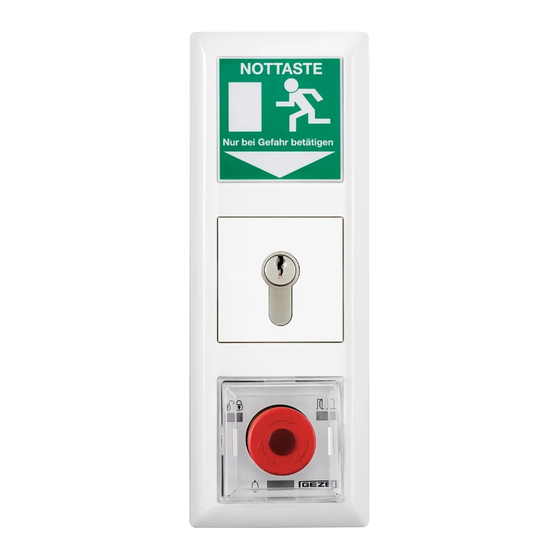
Installation and assembly SECULOGIC TZ320 Fitting the surface-mounted door control unit Open the housing. Fit the wall-mounting bracket near the door (height of emergency button: 850 mm – 1200 mm from floor surface). Take off the mains connection cover. Connect the 230 V cable to the screw terminals of the PSU and refit the cover. -
Page 7: Replacing The Lock Cylinder
SECULOGIC TZ320 Installation and assembly Hook in housing and secure with screws. Fit the cover of the emergency button. Test the unit’s function. Replacing the lock cylinder The lock cylinder must fulfil the following requirements: Profile half-cylinder, 40 mm (30/10) à... -
Page 8: Commissioning
Commissioning SECULOGIC TZ320 Commissioning Preconditions Doors with electrical locks along escape routes must be taken into operation after the manufacturer has certified their suitability for the intended purpose. In addition, the correct installation and correct function of the electri- cal lock must be verified by a specialist. -
Page 9: Description Of Basic Functions
SECULOGIC TZ320 Commissioning Description of basic functions 4.4. 1 Temporary unlocking (KZF) Temporary unlocking releases the emergency door protection for a limited time. During this time, access through the door is possible without triggering an alarm. It is activated with the built-in key switch or an external actuator connected to the Temporary Unlocking input. -
Page 10: Operation
Operation SECULOGIC TZ320 Operation “Locked” LED Door state LED Alarm LED emergency button Indicator Colour Meaning Locked Red flashing (every second) Locked by EMA Green Unlocked Green flashing (every second) Temporary unlocking Green flashing (every two seconds) Unlocked through timer... -
Page 11: Opening Doors In Emergencies And Triggering The Alarm
SECULOGIC TZ320 Opening doors in emergencies and triggering the alarm When the emergency button is pressed the door’s locking elements are de-energized and the door can be opened (direct unlocking). Press the emergency button. LED 1 lights up green and LED 3 lights up yellow. The door is unlocked. -
Page 12: Reading Out Fault Message
Operation SECULOGIC TZ320 Reading out fault message A flashing LED 3 indicates a fault in the system. Connect the service terminal with the door control unit. The fault message is displayed on the service terminal’s display. à Using the table below, determine the fault cause and rectify the fault. - Page 13 SECULOGIC TZ320 Operation Alarm signal Cause of alarm Elimination of alarm cause Emergency unlocking through bus Emergency unlocking through panel, Pull emergency button on panel. VAT etc. Switch off emergency button on VAT. Check BMA and switch off emergency through BMA (bus)
-
Page 14: Terminal Diagram
Max. cable cross-section for screw and plug-in terminals: 1 mm² Terminal field Terminal Function (factory setting) X102 Ribbon cable plug for GEZE key switch without illumination X104 Supply GND Red terminal field 24 V DC supply CAN-H, GEZE bus communication... -
Page 15: Notes About The Terminal Diagram
The notes apply for the following terminal diagram of the various versions of the TZ320. A mains fuse is provided by the owner. GEZE PSU for TZ320N UP = NET220. 500 mA max. 350 mA for peripherals GEZE PSU for TZ320N AP = NT19.2-24. 750 mA max. 650 mA for peripherals Spatially separate primary and secondary side. -
Page 16: Door Control Unit Tz320S, Tz320Sn
Terminal diagram SECULOGIC TZ320 Door control unit TZ320S, TZ320SN On versions BS and BSN key switch SCT320 and illuminated emergency exit sign FWS-B are, in addition, connected with a ribbon cable. GEZE Key switch Connection to TST320 X102 Ribbon cable... -
Page 17: Unlocking Through Bma, Gma Or Rwa
SECULOGIC TZ320 Terminal diagram Unlocking through BMA, GMA or RWA A local emergency button is required TZ320 X106 (orange terminal strip) BMA / GMA / RWA 24 V DC Input 1 (short-term release) Input short-term release) Input 3 (fire alarm system) -
Page 18: Terminal Box Kl220
Terminal diagram SECULOGIC TZ320 Terminal box KL220 Terminal box KL220 can be used to extend the system by four inputs and six outputs. GEZE Key switch Ribbon cable Connection to Clamping box TST320 X102 clamping screw Power supply unit X102... -
Page 19: Appendix
SECULOGIC TZ320 Appendix Appendix Commissioning check list 7. 1 Not fitted Power supply OK Upper edge of all emergency buttons between 850 and 1200 mm from floor surface All emergency button labels applied Cables laid according to DIN VDE 0833, tamper-protected... - Page 20 E-Mail: office-bulgaria@geze.com GEZE GmbH Høje Taastrup Boulevard 53 E-Mail: office-india@geze.com China Niederlassung West 2630 Taastrup Nordsternstraße 65 GEZE Industries (Tianjin) Co., Ltd. Italy Tel. +45(0)46-323324 45329 Essen Shuangchenzhong Road GEZE Italia Srl Fax +45(0)46-323326 Tel. +49 (0) 201-83082-0 Beichen Economic Development Via Giotto, 4 E-Mail: danmark.se@geze.com...
Need help?
Do you have a question about the SECULOGIC TZ320 and is the answer not in the manual?
Questions and answers