GEZE SecuLogic TZ320 Installation And Commissioning Instructions With Connection Diagram
Emergency exit system. door control unit
Hide thumbs
Also See for SecuLogic TZ320:

Related Manuals for GEZE SecuLogic TZ320


Summary of Contents for GEZE SecuLogic TZ320
- Page 1 GEZE SecuLogic Emergency Exit System TZ320 Door Control Unit Installation And Commissioning Instructions With Connection Diagram Material No. 132916 • Rev. 01-2009 • Drawing No. 35207-9-0955...
- Page 2 Document information Document information Document identification Title: Installation And Commissioning Instructions With Connection Diagram GEZE SecuLogic Emergency Exit System TZ320 Door Control Unit Material number: 132916 Revision state: 01-2009 Manufacturer GEZE GmbH Reinhold-Vöster-Str. 21 - 29 71229 Leonberg Germany Telephone:...
-
Page 3: Table Of Contents
Terminal box ........................60 6.13 Locks ..........................64 6.14 Revolving door drive system ...................69 Annex Checklist for commissioning ...................77 Glossary .........................78 Data sheets ........................79 Service menu - service terminal ST220 ................82 Installation And Commissioning Instructions With Connection Diagram GEZE Door Control Unit... -
Page 4: In This Document
GEZE door control unit. 1.1 Product description The GEZE door control unit is an integral part of SecuLogic escape route system and serves for the control and monitor of electric interlocked emergency exits. Furthermore, it offers a wide range of gateways to other products as well as systems. -
Page 5: Abbreviations
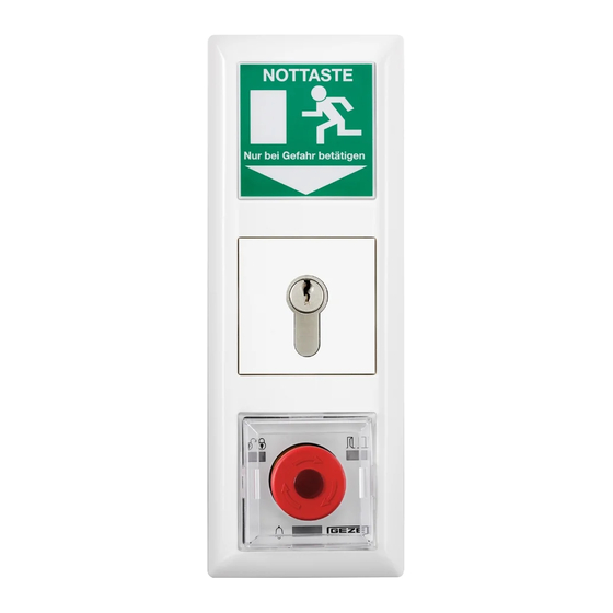
Door control unit with illuminated emergency exit shield and key-operated push button TZ320SN Door control unit with key-operated push button and integrated mains supply circuit On-wall In-wall Fire alarm system Hazard alarm system Installation And Commissioning Instructions With Connection Diagram GEZE Door Control Unit... - Page 6 Motor lock Handle lock TST320 TZ control unit NSA220 Emergency button KL220 Terminal box FTÖ Emergency exit opener Falling lock MA500 Holding magnet TE220 Tableau unit VAT220 Visualisation software Installation And Commissioning Instructions With Connection Diagram GEZE Door Control Unit...
-
Page 7: Safety And Liability
The expert is to issue a certificate on the in-service inspection, which the operator of the building supervisory board has to show on demand. Within the scope of a maintenance contract, the checking can be carried out by a GEZE service technician or a professional organisation authorised by GEZE.... -
Page 8: Installation And Assembly
TZ320BSN, as recommended by GEZE. Illuminated emergency exit shield Frame Mains supply circuit NET220 Terminal strips Ribbon cable Control unit with emergency button TST320 Key-operated push button SCT320 Installation And Commissioning Instructions With Connection Diagram GEZE Door Control Unit... - Page 9 3. Connect and secure the mains supply circuit. 4. Connect the door control system with the key-operated push button and the key- operated push button with the emergency exit shield using the ribbon cable. Installation And Commissioning Instructions With Connection Diagram GEZE Door Control Unit...
- Page 10 5. Plug the terminal strips to the circuit board of the door control system. 6. Set jumper in accordance with the connection diagram (see page 44). 7. Install the door control unit. 8. Check the functional capability. Installation And Commissioning Instructions With Connection Diagram GEZE Door Control Unit...
-
Page 11: Install The On-Wall Door Control Unit
These instructions describe the installation of an on-wall door control unit using the example of TZ320BSN, as recommended by GEZE. TZ320BSN door control unit TZ323BSN door control unit Terminal strips 1. Open the housing. Installation And Commissioning Instructions With Connection Diagram GEZE Door Control Unit... - Page 12 7. Set jumper in accordance with the connection diagram. 8. Secure loose cabling with cable clips. 9. Hook up the housing and bolt. 10. Insert the covering of the emergency button. 11. Check the functional capability. Installation And Commissioning Instructions With Connection Diagram GEZE Door Control Unit...
-
Page 13: Change The Lock Cylinder
5. Change the lock cylinder. 6. Insert a new lock cylinder and fasten with cylinder head screw. 7. Install the door control unit in the inverse order. 8. Check the functional capability. Installation And Commissioning Instructions With Connection Diagram GEZE Door Control Unit... -
Page 14: Commissioning
4.2.2 Switch off the service mode Do not make adjustment nor go to the service menu for three minutes Select end of service mode. Door control unit is in normal state again. Installation And Commissioning Instructions With Connection Diagram GEZE Door Control Unit... -
Page 15: Connect The Service Terminal St220 With The Door Control Unit
The first level of the service menu is displayed. 4.4 Switch off the service terminal Do not press any button for two minutes. The service terminal is switched off. Installation And Commissioning Instructions With Connection Diagram GEZE Door Control Unit... -
Page 16: System Settings
English In the service menu, select system setup > language > choice and set the language. The service menu is displayed in the selected language. Installation And Commissioning Instructions With Connection Diagram GEZE Door Control Unit... -
Page 17: Door Control Unit Settings
The selected value is displayed on the upper display row of the service terminal. In order to avoid an inadvertent continuous unlocking in highly frequented doors, use an external control device for the short-term release. Installation And Commissioning Instructions With Connection Diagram GEZE Door Control Unit... - Page 18 2. Set times for pre-alarm and alarm. 3. Set buzzer for alarm, pre-alarm and sabotage. The selected value is displayed on the upper display row of the service terminal. Installation And Commissioning Instructions With Connection Diagram GEZE Door Control Unit...
- Page 19 2. For the corresponding input number, choose KL input 1-4 > activity KL1-4 > choice and select activity (default setting: high-active). The selected value is displayed on the upper display row of the service terminal. Installation And Commissioning Instructions With Connection Diagram GEZE Door Control Unit...
- Page 20 The outputs of the door control units and terminal boxs can be set on the following contacts: Contact Parameter Specification Closer Contact closes Opener Contact opens Disabled The output is not controlled – Installation And Commissioning Instructions With Connection Diagram GEZE Door Control Unit...
- Page 21 Contact closes when the emergency button on TZ320 is actuated and during indirect release Opener NC Contact opens when the emergency button on TZ320 is actuated and during indirect release Installation And Commissioning Instructions With Connection Diagram GEZE Door Control Unit...
- Page 22 Contact is opened, as long as the emergency button on TZ320 is actuated Short-term unlock Closer NO Contact is closed, if the system is short-term unlocked Opener NC Contact is opened, if the system is short-term unlocked Installation And Commissioning Instructions With Connection Diagram GEZE Door Control Unit...
-
Page 23: Components Settings
Set inputs/outputs The setting of the inputs/outputs conforms with the setting of the door control unit (see page 19). Installation And Commissioning Instructions With Connection Diagram GEZE Door Control Unit... - Page 24 The selected value is displayed on the upper display row of the service terminal. 4.7.4 Set inverse door drive If a revolving door drive system GEZE TSA160NT is connected inversely, the inverse door drive must be set on available. The drive system undertakes the control of the emergency exit opener.
- Page 25 Time-switch interruptible on public holidays In order to be able to interrupt the time-switch during public holidays, an input must be set on public holiday and a switch connected to this. Installation And Commissioning Instructions With Connection Diagram GEZE Door Control Unit...
-
Page 26: Bus Settings
(acoustic via integrated buzzer and optical via integrated LED). The system remains unlocked until the signal is no longer available and the alarm was reset on- site on TE220 or on the VAT via the key-operated push button. Installation And Commissioning Instructions With Connection Diagram GEZE Door Control Unit... - Page 27 TE220 or the VAT220SN. In the service menu select and set bus configuration > emergency unlock. The selected value is displayed on the upper display row of the service terminal. Installation And Commissioning Instructions With Connection Diagram GEZE Door Control Unit...
- Page 28 In the service menu select and set bus configuration > sluice > allocation > group1-10 > choice (default setting: not assigned). The selected value is displayed on the upper display row of the service terminal. Installation And Commissioning Instructions With Connection Diagram GEZE Door Control Unit...
-
Page 29: Operation
Green flashing (every second) Short-term release Green flashing (every 2 seconds) Unlocked via time-switch Door closed Green Door open Yellow Alarm Yellow flashing (every second) Pre-alarm Yellow flashing Fault Installation And Commissioning Instructions With Connection Diagram GEZE Door Control Unit... -
Page 30: Control Tz320 Door Control Unit Via Key-Operated Push Button
2. Turn the key right and hold approximately for a second. LEDs1 and 2 flash red. The door is locked. One sluice function switched off for this door is engaged again when locking. Installation And Commissioning Instructions With Connection Diagram GEZE Door Control Unit... -
Page 31: Open The Doors And Trigger Off The Alarm In Case Of An Emergency
If a connected fire alarm system or the like is triggered off, the interlocking elements are automatically switched off (emergency unlock). Press emergency button LED 1 flashes green and LED 3 flashes yellow. The door is unlocked. Alarm is triggered off. Installation And Commissioning Instructions With Connection Diagram GEZE Door Control Unit... -
Page 32: Cancel Alarm
In addition, the door alarm can be acknowledged via the outputs short-term unlock . A sabotage alarm can only be acknowledged 30 seconds after the cause of the alarm is acknowledged. Installation And Commissioning Instructions With Connection Diagram GEZE Door Control Unit... -
Page 33: Read Out The Alarm Memory Via The Service Terminal
Door alarm INVAL Invalid Fault reports Memory entry Description INIT Init KL485 Communication terminal box TT485 Communication door control unit MAINS Mains return CLOCK Clock EEPROM EEPROM INVAL Invalid Installation And Commissioning Instructions With Connection Diagram GEZE Door Control Unit... -
Page 34: Read Out Fault Report
Correct data in the service Invalid clock/date Invalid values for the date and time menu Change the door control unit EEPROM error EEPROM cannot be read out Installation And Commissioning Instructions With Connection Diagram GEZE Door Control Unit... -
Page 35: Read Out Alarm Signal
Check the input of the corresponding door control unit Indirect release Mains supply Indirect release via door control Reset the emergency button circuit TT pressed unit on the door control unit Installation And Commissioning Instructions With Connection Diagram GEZE Door Control Unit... -
Page 36: Power Failure
5.7 Power failure The escape route system GEZE SecuLogic saves the active preset mode of operation in a non-volatile memory (EEPROM), so that it also becomes active after a power failure. Components (KL, TT etc.) that are not switched off are automatically recognised. -
Page 37: Reset Door Control Unit To Default Setting
1. Activate service mode and connect service terminal with the door control unit. 2. In the service menu, select diagnosis > version > display. The software version of the door control unit is displayed. Installation And Commissioning Instructions With Connection Diagram GEZE Door Control Unit... - Page 38 Operation Installation And Commissioning Instructions With Connection Diagram GEZE Door Control Unit...
-
Page 39: Terminal Connection Diagram 6.1 Contents
KL220 terminal box (terminals and locking devices) KL220 terminal box Locks ..........................64 Handle lock HLS Motor lock MLS Revolving door drive system ..................69 Revolving door drive system TSA160NT Revolving door drive system Slimedrive EMD Installation And Commissioning Instructions With Connection Diagram GEZE Door Control Unit... -
Page 40: Preface
CTI Control unit TST320 Signal light SLE KL220 terminal box Flashing light BLE220 TT220 door control unit Signal horn with flashing light Holding magnet MA500 Alarm horn SLH220 Installation And Commissioning Instructions With Connection Diagram GEZE Door Control Unit... -
Page 41: Door Control Units
1 2 3 4 to terminal 7 + 8 of terminal box X107 CAN load resistance set (delivery status) CAN load resistance not set Installation And Commissioning Instructions With Connection Diagram GEZE Door Control Unit... - Page 42 COM, adjustable output 2 (Door-o. op.cur., closer) NO/NC, adjustable output 2 max. 1 A, 30 V DC Locking device Description Value Specification 1,5 A, SMF 125 V, 24 V external swift Installation And Commissioning Instructions With Connection Diagram GEZE Door Control Unit...
-
Page 43: Instructions For The Terminal Connection Diagram
1) The mains fuse takes place on site. 2) GEZE mains supply circuit in TZ320N UP = NET220. 500 mA max. 350 mA for peripherals GEZE power supply unit in TZ320N AP = NT19.2-24. 750 mA max. 650 mA for peripherals... -
Page 44: Door Control Unit Tz320Bs, Tz320Bsn
NO/ (NC) output 1 (alarm) 24 V DC COM output 2 (max. 30 V, 1 A) NO/ (NC) output 2 For instructions regarding the connection diagram see page 43. Installation And Commissioning Instructions With Connection Diagram GEZE Door Control Unit... -
Page 45: Door Control Unit Tz320, Tz320N
NO/ (NC) output 1 (alarm) 24 V DC (Option) COM output 2 (max. 30, V 1 A) NO/ (NC) output 2 For instructions regarding the connection diagram see page 43. Installation And Commissioning Instructions With Connection Diagram GEZE Door Control Unit... -
Page 46: Door Control Unit Tz320B, Tz320Bn
NO/ (NC) output 1 (alarm) 24 V DC (Option) COM output 2 (max. 30 V, 1 A) NO/ (NC) output 2 For instructions regarding the connection diagram see page 43. Installation And Commissioning Instructions With Connection Diagram GEZE Door Control Unit... -
Page 47: Door Control Unit Tz320S, Tz320Sn
Signal light Alarm siren NO/ (NC) output 1 (alarm) 24 V DC (Option) COM output 2 NO/ (NC) output 2 For instructions regarding the connection diagram see page 43. Installation And Commissioning Instructions With Connection Diagram GEZE Door Control Unit... -
Page 48: Geze Bus
Maximum length per BUS line = 900 m Maximum number of members per BUS line = 63 The load resistance must be set in the first and last members in the BUS assembly Installation And Commissioning Instructions With Connection Diagram GEZE Door Control Unit... -
Page 49: Geze Bus With Te220, Vatsn220 And Tz320
The load resistance must be set in the first and last members in the BUS assembly The arrangement of the members can be arbitrary. The tableau and VAT220SN can be arranged at any desired location in the BUS system Installation And Commissioning Instructions With Connection Diagram GEZE Door Control Unit... -
Page 50: Safety Circuit (Indirect Release)
2) Condense the wires in the connection room. Maximum length of the safety circuit = 400 m Current drain for the safety circuit per TZ320 approx. 20 mA Installation And Commissioning Instructions With Connection Diagram GEZE Door Control Unit... -
Page 51: Interlocking Elements
X106 (orange terminal strip) MA500 MA500 Locking mechanism + Locking mechanism - Door locked 24 V DC Door closed Door contact Door contact Contact closed, if the door is closed Installation And Commissioning Instructions With Connection Diagram GEZE Door Control Unit... -
Page 52: Emergency Exit Opener Typ331U Din Right/Left (1-Flanked Doors)
6.8.5 Emergency exit opener TYP331 DIN right/left (1-flanked doors) TST320 FTÖ331 FTÖ331 X106 (orange terminal strip) right DIN left DIN Locking mechanism + Locking mechanism - Door locked 24 V DC AKRR Door closed 24 V DC Installation And Commissioning Instructions With Connection Diagram GEZE Door Control Unit... -
Page 53: Emergency Exit Opener Typ331 Din Right (2-Flanked Doors)
TST320 FTÖ332 X106 (orange terminal strip) Locking mechanism + Locking mechanism - Door closed 24 V DC 24 V DC Door locked AKRR Relay circuit board RP220, No. 102355 Installation And Commissioning Instructions With Connection Diagram GEZE Door Control Unit... -
Page 54: Emergency Exit Opener Typ332 (2-Flanked Doors)
X106 (orange terminal strip) FTÖ332 FTÖ332 Locking mechanism + Locking mechanism - Door closed 24 V DC 24 V DC AKRR Door locked AKRR Relay circuit board RP220 Relay circuit board RP220 Installation And Commissioning Instructions With Connection Diagram GEZE Door Control Unit... -
Page 55: Emergency Button
FTÖ 331U! 1) Only emergency buttons authorised by GEZE must be used. 2) Set jumper 1-2 of TST320 on external voltage supply. 3) Condense the wires in the connection room. Installation And Commissioning Instructions With Connection Diagram GEZE Door Control Unit... - Page 56 If input 3 is allocated, entries 1 and 2 of the door control unit as well as entries 1 to 4 of KL220 can also be used for this function. Installation And Commissioning Instructions With Connection Diagram GEZE Door Control Unit...
-
Page 57: Key-Operated Push Button
In the default setting, inputs 1 and 2 are set on "short-term unlock", that means that control devices can be connected to these inputs Set the output accordingly if the control devices for short-term unlock are connected to output 3 Installation And Commissioning Instructions With Connection Diagram GEZE Door Control Unit... -
Page 58: Key-Operated Push Button With Display Sct222
X105 (black terminal strip) 24 V DC SCT lock, short-term release, acknowledge SCT unlock, acknowledge Left contact Note see page 43. SCT222 UP No. 100064 SCT222 AP No. 100065 Installation And Commissioning Instructions With Connection Diagram GEZE Door Control Unit... -
Page 59: Numerical Code Lock
In the default setting, inputs 1 and 2 are set on "short-term unlock", that means that control devices can be connected to these inputs. Set the output accordingly if the control devices for short-term unlock are connected to output 3 Installation And Commissioning Instructions With Connection Diagram GEZE Door Control Unit... -
Page 60: Terminal Box
Indicators Operating LED Locking device Description Value Specification 1 A, SMF 125 V, swift 24 V external Reserve (Res) 1 A, SMF 125 V, swift 24 V external Installation And Commissioning Instructions With Connection Diagram GEZE Door Control Unit... - Page 61 COM adjustable output 5 NC adjustable output 5 NO adjustable output 6 (System fault, closer) max. 1 A, 30 V DC COM adjustable output 6 NC adjustable output 6 Installation And Commissioning Instructions With Connection Diagram GEZE Door Control Unit...
- Page 62 COM output 1 Alarm siren NO-output 6 NC output 1 (alarm) (System fault) COM-output 6 (Closer) NC-output 6 (Option) 24 V DC COM output 2 NO/ (NC) output 2 Installation And Commissioning Instructions With Connection Diagram GEZE Door Control Unit...
- Page 63 Terminal connection diagram 1) The mains fuse takes place on site. 2) GEZE mains supply circuit NT19.2-24. 600 mA max. for periphery protection class II The voltage supply of TZ320 must take place via the mains supply circuit of KL220.
-
Page 64: Locks
TST320 (terminals 2 + 52 or 53). Mode of operation: "Pre-alarm" is triggered off when the handle is activated in locked door control unit. For this function, set the input of TST on "handle". Installation And Commissioning Instructions With Connection Diagram GEZE Door Control Unit... - Page 65 For this function, set the input of TST on "handle". In order to couple the lock for the duration of the short-term release time set on the door control unit, set output 2 of TST320 on "short-term unlock". Installation And Commissioning Instructions With Connection Diagram GEZE Door Control Unit...
- Page 66 3 - 8 seconds = unlock > 8 seconds = service mode (Details from the state "unlock". In the case of an unlocked system, it is, first of all, locked.) Installation And Commissioning Instructions With Connection Diagram GEZE Door Control Unit...
-
Page 67: Motor Lock Mls
TST320 (terminals 2 + 52 or 53). Mode of operation: "Pre-alarm" is triggered off when the handle is activated in a locked door control unit. For this function, set the input of TST on "handle". Installation And Commissioning Instructions With Connection Diagram GEZE Door Control Unit... - Page 68 TST320 (terminals 2 + 52 or 53). Mode of operation: "Pre-alarm" is triggered off when the handle is activated in a locked door control unit. For this function, set the input of TST on "handle". Installation And Commissioning Instructions With Connection Diagram GEZE Door Control Unit...
-
Page 69: Revolving Door Drive System
COM output 1 AUT Automatic NO output 1 (OM drive) 24 V DC 24 V DC COM output 2 24 V DC NO output 2 (drive control) Contact sensor authorised Installation And Commissioning Instructions With Connection Diagram GEZE Door Control Unit... - Page 70 In connecting the program switch DPS or TPS, connect output 1 of the door control unit (OM drive) to the adjustable input PE1 or PE2. On the DCU5, set the input PE on "night". On TZ320, set output 1 on "opener". Installation And Commissioning Instructions With Connection Diagram GEZE Door Control Unit...
- Page 71 3) Output 1 = "door drive system mode of operation". 4) Output 2 = "door drive system control". 5) Bridge circuit set in the original condition. Remove the bridge circuit in the event of an indirect release. Installation And Commissioning Instructions With Connection Diagram GEZE Door Control Unit...
- Page 72 The setting of the outputs is identical with the settings of the door control unit. Use the terminals COM and NO in outputs with change-over relay (outputs 4, 5 and 6). Installation And Commissioning Instructions With Connection Diagram GEZE Door Control Unit...
- Page 73 Internal program switch on position "1" = drive system "permanent opening" Internal program switch on position "2" = drive system "automatic" Internal program switch on position "0" = drive system "night" Installation And Commissioning Instructions With Connection Diagram GEZE Door Control Unit...
-
Page 74: Revolving Door Drive System Slimedrive Emd
1) The mains fuse takes place on site. 2) In 2-flanked, connect the door drive systems to the control system of the operation flank. 3) Set output 1 on "door drive system mode of operation". Installation And Commissioning Instructions With Connection Diagram GEZE Door Control Unit... - Page 75 EMD. The setting of the outputs is identical with the settings of the door control unit. Use the terminals COM and NO for outputs with change-over relay (outputs 4, 5 and 6). Installation And Commissioning Instructions With Connection Diagram GEZE Door Control Unit...
- Page 76 Internal program switch on position "1" = drive system "permanent opening" Internal program switch on position "2" = drive system "automatic" Internal program switch on position "0" = drive system "night" Installation And Commissioning Instructions With Connection Diagram GEZE Door Control Unit...
-
Page 77: Annex
External alarm device / external alarm device combination is functional Emergency-power supply USV is functional Tableau unit is functional, visualisation is in order Signal messages on the superordinate building control Correct cable laying in indirect release Installation And Commissioning Instructions With Connection Diagram GEZE Door Control Unit... -
Page 78: Glossary
The setting post trigger can be disabled via the service menu. In a running release time, the system locks again if a short-term release is triggered once again with the internal key-operated push button or a programmable input. Installation And Commissioning Instructions With Connection Diagram GEZE Door Control Unit... -
Page 79: Data Sheets
-10 to 50 °C Guidelines "Guidelines on electric locking systems of doors in escape routes (EltVTR) - version December 1997" Packaging contents Control unit, connection terminals and spare fuse Installation And Commissioning Instructions With Connection Diagram GEZE Door Control Unit... - Page 80 Guidelines "Guidelines on electric locking systems of doors in escape routes (EltVTR) - version December 1997" Packaging contents Mounting plate, pre-assembled housing, mounting accessories, connection terminals and spare fuse Installation And Commissioning Instructions With Connection Diagram GEZE Door Control Unit...
- Page 81 EN 60 950 (in installed state) Range of application Dry rooms Climate conditions -10 to 50 °C Packaging contents Key-operated push button module, connection terminal and spare fuse Installation And Commissioning Instructions With Connection Diagram GEZE Door Control Unit...
-
Page 82: Service Menu - Service Terminal St220
7.4 Service menu - service terminal ST220 1. Menu level 2. Menu level 3. Menu level 4. Menu level 5. Menu level 6. Menu level Choice (default setting) TZ parameter Short-term Duration Change value 0s..infinite (10s) unlock Abort (Yes) Post trigger (Yes) Alarm Alarm time... - Page 83 1. Menu level 2. Menu level 3. Menu level 4. Menu level 5. Menu level 6. Menu level Choice (default setting) Custom inputs TZ input1 Configuration TZ1 Choice Sabotage ext. Unlock Lock Short-term unlock Burglar alarm system Time-switch Fire alarm system Motor lock Handle Public holiday...
- Page 84 1. Menu level 2. Menu level 3. Menu level 4. Menu level 5. Menu level 6. Menu level Choice (default setting) TZ output2 Configuration TZ2 Choice Door-o. op.cur. Contact TZ2 Choice (Closer) System Available Choice Available environment Unavailable (Unavailable) Custom inputs KL input1 Configuration KL1 Choice...
- Page 85 1. Menu level 2. Menu level 3. Menu level 4. Menu level 5. Menu level 6. Menu level Choice (default setting) Custom outputs KL output1 Configuration KL1 Choice Door state OM control Drive control Alarm Release Release direct Release indirect Door alarm Sabotage alarm Pre-alarm...
- Page 86 1. Menu level 2. Menu level 3. Menu level 4. Menu level 5. Menu level 6. Menu level Choice (default setting) Choice (Inactive) Choice (Active) Choice (Active) Automatic Choice Available Inverse Unavailable (Unavailable) Time-switch Time-switch1 Clock start Hour Change value 0..23 (0) Minute Change value...
- Page 87 1. Menu level 2. Menu level 3. Menu level 4. Menu level 5. Menu level 6. Menu level Choice (default setting) Minute Change value 0..59 (0) Days Installation Choice Active Inactive (Active) Tuesday Choice (Active) Wednesday Choice (Active) Thursday Choice (Active) Friday Choice...
- Page 88 1. Menu level 2. Menu level 3. Menu level 4. Menu level 5. Menu level 6. Menu level Choice (default setting) Group3 Choice (Bus function off) Group4 Choice (Bus function off) Group5 Choice (Bus function off) Fire alarm Group1 Choice (Bus function off) system Group2...
- Page 89 Annex Installation And Commissioning Instructions With Connection Diagram GEZE Door Control Unit...
- Page 90 Finland Austria E-mail: leonberg.de@geze.com P.O. Box 7934, Midrand 1685 GEZE Finland South Africa GEZE Austria GmbH Branch office of GEZE Scandinavia AB Tel. ++27 11 3158286 Mayrwiesstraße 12 Subsidiary companies Postbox 20 Fax. ++27 11 31558261 5300 Hallwang b. Salzburg Herraliantie 824 E-mail: info@dclsa.co.za...
Need help?
Do you have a question about the SecuLogic TZ320 and is the answer not in the manual?
Questions and answers