Table of Contents
Advertisement
Advertisement
Table of Contents

Related Manuals for GEZE MBZ300


Summary of Contents for GEZE MBZ300
- Page 1 230V 230V 230V 230V 230V 230V MBZ300 MBZ300 MBZ300 MBZ300 MBZ300 MBZ300 MBZ300 MBZ300 MBZ300 MBZ300 MBZ300 MBZ300 MBZ300 MBZ300 MBZ300 Reset Reset MBZ300 EN Installation instructions Emergency power supply unit 137265-02...
-
Page 2: Table Of Contents
Components of the MBZ300 control unit ..............................6 Standard central units .....................................7 Object-specifically configured control units ............................7 Installation .................................8 Equipment and configuration of the MBZ300 central unit .......................8 Connection of the MBZ300 control unit ..............................12 Installing the CAN module ..................................18 commissioning ..............................20 Operation ................................ -
Page 3: Symbols And Means Of Representation
The specifications in this description always refer to the factory standard configuration. Changes in the software configuration of the control unit may only be carried out by qualified personnel trained by GEZE. A warranty claim against the manufacturer or distributor of the control unit does not exist for damage that is due to interventions in the control unit which are not authorised by the manufacturer or its distributor. - Page 4 Secure workplace against unauthorised entry. Ensure that mounting, commissioning and maintenance are only carried out by qualified personnel authorised by GEZE. If unauthorised changes are made to the system, GEZE cannot be made liable in any way whatsoever for any resulting damages.
-
Page 5: Behaviour In The Event Of A Fire
With the emergency power supply unit rooms are ventilated and in case of a fire smoke extracted automatically. The MBZ300 emergency power supply unit fulfills sound engineering practice and conforms to the applicable safety regulations. The system is designed solely for use in dry rooms. -
Page 6: Properties
à Thanks to the possibilities of the software configuration and the extensive field of application of the modules, special installations in the central unit are hardly necessary for special applications. Components of the MBZ300 control unit 2.4.1 Power supply (depending on the version) à... -
Page 7: Standard Central Units
After the standard control units, the object-specifically pre-configured control units (mat. no. 137453) are availa- ble from GEZE. A wide range of configurations can be selected for these control units, e.g. à service range and housing size as per the basic control unit (N10, N24 …) à... -
Page 8: Installation
Introduce the lines through the cable glands in the central unit. Connect external components. Equipment and configuration of the MBZ300 central unit Overview of the modules and components à Power module PM à Power module extension PME à... - Page 9 72 A 100 mA 300 mA SNT = switching power supply unit Observe the control cabinet size when selecting the batteries. Examples for the selection of the required battery capacity at MBZ300 standard central units: Rechargeable N48K N48G battery capacity...
- Page 10 Installation MBZ300 3.1.2 Space required for the modules and components on the DIN rail (width) Modules à Control module CM, Sensor module SM, Relay module , DME ERM, Drive module DM, Weather module WM à approx. 23 mm à Power module PM, Power module extension PME, DME à...
- Page 11 MBZ300 Installation 3.1.4 Layout of the modules on the DIN rail It is imperative that the module layout on the DIN rail be observed. Place the modules on the DIN rail in the following order directly next to each other (from left to right): à...
-
Page 12: Connection Of The Mbz300 Control Unit
Installation MBZ300 Connection of the MBZ300 control unit The following three connection types exist for the modules: à Supply voltage à Power module PM à Power module extension PME à Drive module DM à BUS connection (ribbon cable) à All the modules (only connection PME – PM on the module top, remaining modules on the bottom) à... - Page 13 MBZ300 Installation Connection with two switching power supply units Safety Safety Sicherung Sicherung 3 2 1 33 32 1 52 51 1 Operating display (green) Operating display (green) Betriebsanzeige (grün) Betriebsanzeige (grün) 24 A Status display (green) Fault display (yellow) Statusanzeige (grün)
- Page 14 Installation MBZ300 Connection with three switching power supply units Safety Safety Sicherung Sicherung 3 2 1 33 32 1 52 51 1 Operating display (green) Operating display (green) Betriebsanzeige (grün) Betriebsanzeige (grün) Status display (green) Fault display (yellow) 24 A Statusanzeige (grün)
- Page 15 MBZ300 Installation 3.2.2 Connection of the internal BUS connection The BUS connections of the modules for the ribbon cable are located on the bottom (only connection PME to PM on the module top). The modules can be connected with each other irrespective of their function in the system (digital BUS system).
- Page 16 Installation MBZ300 3.2.3 Connection and installation of the batteries CAUTION! Incorrectly connected batteries can cause damage to property. When connecting the batteries ensure that the polarity is correct. Connecting cable + (red) Connecting cable – (blue) Ring cable lug with cable...
- Page 17 MBZ300 Installation 3.2.5 Connecting external components Ensure that the electrical installation is carried out in accordance with the applicable regulations and guide- lines. For low voltages use only cables without protective conductor. Power module PM Control module CM/Sensor module SM...
-
Page 18: Installing The Can Module
Installation MBZ300 The cable cross-section for the drives depends on the type and number of drives. However, it has to amount to at least 1.5 mm . A cable up to max. 2.5 mm can be terminated to the drive module DM; larger cross-sections have to be connected via additional series terminals. - Page 19 MBZ300 Installation Setting the jumper First control unit Control unit(s) Last control unit Insert the jumper (terminator) Erste Zentrale Zentrale(n) Letzte Zentrale in the first and last control units With jumper Without jumper With jumper Mit Jumper Ohne Jumper Mit Jumper linked via the CAN-bus.
-
Page 20: Commissioning
Automatic opening and closing (e.g. wind-rain control) takes priority over manual operation. Venting mode The service technician can set parameters for several functions using the MBZ300 configuration software. Opening and closing windows The windows are divided into ventilator groups. Each ventilator group has one or more vent switches with which you can open and close the windows of the ventilator group together. -
Page 21: Alarm Operation
MBZ300 Operation Opening width restriction The service technician can specify a time-controlled opening width limitation of the windows separately for each drive module. When the drives receive an Open signal via the vent switch, they stop after the specified opening time. - Page 22 Operation MBZ300 Resetting the system completely The method for resetting the RWA emergency power supply unit depends on the cause of the alarm. By an RWA switch: Reset the RWA switch. By a smoke detector or by a heat differential detector: Reset the smoke detector line and RWA switch.
-
Page 23: Power Failure And Fault
à If necessary, replace the fuse. à In case of faults despite an intact power supply, contact a specialist authorised by GEZE. Fault Work in the control cabinet is required in case of a fault with a yellow illuminated fault LED. -
Page 24: Module Description
Module description MBZ300 Module description Power module PM Functions: à Monitoring of the mains power supply 230V à Checking of the battery charge voltage 230V à Switching over to battery operation in case of power failure à Connection for sensor used to monitor the battery... - Page 25 MBZ300 Module description Power module PM connections System voltage (battery-.buffered) Power pack voltage Fuse 25 A Connection to PME 1 Operating display (green) Status display (green) Fault display (yellow) blue Sensor for to next battery temperature to CM blue blue...
-
Page 26: Power Module Extension Pme
Module description MBZ300 Power module extension PME Functions: à Monitoring of the mains power supply in case of more than one switching power supply unit 230V à Switching over to battery operation in case of power 230V failure à VdS tested... -
Page 27: Control Module Cm
MBZ300 Module description Control module CM Functions: à Monitoring of three smoke alarm lines for triggering and faults à Processing of the signals of vent switches à Connections for external LED displays (operation, fault, alarm and "Window opening") à Basic equipment of the central unit (direct connection... - Page 28 Module description MBZ300 Symbol Status Operating mode/Fault Yellow, 3 x flash CAN participant missing Green, continuously External display "Window opening" on All the windows in the fire RWA button compartment closed Yellow, lights up continuously At least 1 ventilator group in the fire...
- Page 29 MBZ300 Module description Control module CM connections Last RWA switch FT4 1. Smoke detector Last smoke detector 1. Rauchmelder Letzter Rauchmelder max. 10 RWA key Letzter RWA-Taster FT4 max. 10 RWA-Taster Leave termination Endwiderstände 22 k in line in Linie resistors 22 kΩ...
-
Page 30: Sensor Module Sm
Module description MBZ300 Sensor module SM Functions: à Monitoring of three smoke alarm lines for triggering and faults à Processing of the signals of vent switches à Connections for external LED display (operation, fault, alarm and "Window opening") à Use only possible at an existing control module CM MBZ300 à... - Page 31 MBZ300 Module description Sensor module SM connections Last RWA switch FT4 1. Smoke detector Last smoke detector Letzter RWA-Taster FT4 max. 10 RWA key 1. Rauchmelder Letzter Rauchmelder max. 10 RWA-Taster Leave termination in line Endwiderstände 22 k in Linie resistors 22 kΩ...
-
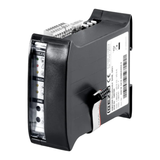
Page 32: Drive Module Dm / Dme
Module description MBZ300 Drive module DM / DME Functions: à Connection for motorised drives up to max. of 10 A/ DME 20 A à Monitoring of the drive power through closed-circuit current (for fault, short-circuit, interruption) à Processing of the signals of vent switches (if required... - Page 33 MBZ300 Module description 6.5.1 Drive module DM / DME connections Lüftungstaster LTA-24-AZ Configurable inputs Parametrierbare Eingänge Antriebe 24 V DC, max. 10 A / DME max. 20 A Drives 24 V DC, max. 10 A / DME max. 20 A...
- Page 34 Module description MBZ300 6.5.2 IQ window drives connection with differentiation between ventilation and RWA mode The detector relays must be configured to "Alarm" and assigned to individual fore sections.
- Page 35 MBZ300 Module description 6.5.3 Drive module DME connection diagram Standard drive connection or IQ window drives connection with differentiation between ventilation and RWA mode Isolate 1. Motor 2nd Motor Last motor 1. Motor 2. Motor Letzter Motor Conduc- Ader 3...
-
Page 36: Weather Module Wm
Module description MBZ300 Weather module WM Functions: à Connections for 1 wind and rain sensor each à Wind direction sensor for wind-dependent opening and closing in case of fire à Processing of the signals of external ventilation control units à Connections for external signal transfer... - Page 37 MBZ300 Module description Connection of a wind and rain sensor set (mat. no. 140229) to the weather module WM GC 401 RS GC 401 RS GC 402 WVS GC 402 WVS GC 401 RS GC 402 WVS GC 401 RS...
- Page 38 Module description MBZ300 Required sensors: à Wind direction sensor GC 403 WDS (mat. no. 140228) à Wind and rain sensor set GC 401 RS and GC 402 WVS (mat. no. 140229) Connection off rain/wind control (mat. no. 091529) "Wind" input must be configured to switching contact setting.
-
Page 39: Relay Module Erm
MBZ300 Module description Relay module ERM The relay module ERM must be configured with the MBZ 300 software. 6.7.1 Functions à 6 parameterisable relay outputs à Notification of error and operating statuses MBZ300 Operation (green) Fault (yellow) Display Symbol Status... -
Page 40: Overview Of The Displays
Overview of the displays MBZ300 Overview of the displays WARNING! Danger of fatal injury in case of malfunctions during a fire! The system and its display elements have to function correctly. Eliminate all the faults immediately. Displays: Displays: Displays: Operation... -
Page 41: Module Configuration
MBZ300 Module configuration Alarm triggering / EMERGENCY OPEN Display element/Symbol Display Red (at modulesCM, SM and DM of the corresponding fire compartment) Red; indicates for which drive module DM the smoke and heat extraction units are opened EMERGENCY CLOSE (closing of the smoke and heat extraction units) is possible with the RWA switch. Smoke detectors have to be reset using the Reset switch on the control or sensor module. -
Page 42: After-Sales Service Maintenance
Problem Cause Measure Fault LED at the RWA switch lights up Fault Contact a specialist authorised by GEZE. or flashes yellow. Fault LED at the RWA switch flashes Mains power failure Have the power supply to the RWA emergen- yellow/briefly (0.1 s). -
Page 43: Storage
Please return waste batteries to a communal collection site or retail collection location. Following use, you may return by mail any batteries received from us. The address is: GEZE GmbH, Incoming Goods, Reinhold-Vöster-Str. 21–29, 71229 Leonberg/Germany. -
Page 44: Technical Data
Technical data MBZ300 Technical data Electrical data and connection values Operating voltage (primary) 195…253 V AC Frequency 50…60 Hz Pre-fuse 16 A Power consumption 240 W (N10), 480 W (N24), 960 W (N48), 1440 W (N72) Output voltage for drives 24 V DC ±5 %;... -
Page 45: 13.1 Fuses
MBZ300 Technical data 13.1 Fuses Overview of the modules and fuses (respectively at the module top) Module Safety Power module PM F1 = 25 A (flat-type automobile fuse ISO 8820-3) Power module extension PME 1 F2 = 25 A (flat-type automobile fuse ISO 8820-3) -
Page 46: Declaration Of Conformity
Declaration of conformity MBZ300 Declaration of conformity... - Page 47 MBZ300 Declaration of conformity...
- Page 48 97944 Boxberg-Schweigern Tel. +49 (0) 7930 9294 0 Baltic States Iberia Singapore Fax +49 (0) 7930 9294 10 GEZE GmbH Baltic States office GEZE Iberia S.R.L. GEZE (Asia Pacific) Pte, Ltd. E-Mail: sk.de@geze.com E-Mail: office-latvia@geze.com E-Mail: info@geze.es E-Mail: gezesea@geze.com.sg www.geze.com...
Need help?
Do you have a question about the MBZ300 and is the answer not in the manual?
Questions and answers