Table of Contents
Advertisement
Quick Links
Advertisement
Table of Contents

Subscribe to Our Youtube Channel
Related Manuals for Mitel StreamLine


Summary of Contents for Mitel StreamLine
- Page 1 Mitel StreamLine HARDWARE INSTALLATION GUIDE Release 1.1...
- Page 2 Mitel makes no warranties regarding the content of this document. Mitel is not responsible for any loss or damages arising from the use or misuse of this document. The information contained in this document as well as all product specifications are subject to change without notice.
- Page 3 Service and Support Mitel is dedicated to customer satisfaction and the high quality of its products. Our technical support team is prepared to assist you in maximizing the efficiency and dependability of your StreamLine switch environment, and will provide you with an immediate solution should a problem with your product arise.
- Page 4 A caution contains an instruction that the reader must follow in order to prevent damage to equipment, network failure or loss of data. Example: CAUTION: Do not expose the StreamLine switch or any of its components to a magnetic field or electrostatic charge. Damage to system components could result.
-
Page 5: Table Of Contents
Mitel StreamLine Switch - Hardware Installation Guide CHAPTER 1 PRODUCT DESCRIPTION ..............1 Quick Links ..........................1 ® Mitel StreamLine 24-Port and 48-Port Switches ................1 Mitel StreamLine 8-Port Switch......................1 Introduction ..........................2 StreamLine Family of Switches ....................3 StreamLine 24-Port and 48-Port Switches .................... - Page 6 AC Connection ..........................40 Back Up Power..........................41 UPSs ..............................41 Multiple Unit Configurations......................... 42 Daisy-chaining Mitel StreamLine Units for Power Supply Redundancy ..........42 Replacing the Power Supply Unit ......................45 StreamLine 8-Port Switch ......................47 Before You Install..........................47 Physical Location Requirements......................
- Page 7 50-port Wiring Harness ........................53 APPENDIX A VERIFYING WIRING AND CABLING............ 56 Verifying the Wiring Plant ......................56 StreamLine 24-Port and 48-Port Switches Uplink Ports..............56 StreamLine 8-Port Switch Uplink Ports....................56 All StreamLine Switches Downlink Ports..................... 57 Verifying the Cabling Plant ...................... 57 APPENDIX B ACRONYMS AND ABBREVIATIONS ...........
- Page 8 Mitel StreamLine Switch - Hardware Installation Guide viii...
-
Page 9: Chapter 1 Product Description
Mitel StreamLine Switch - Hardware Installation Guide Chapter 1 PRODUCT DESCRIPTION QUICK LINKS ® MITEL STREAMLINE 24-PORT AND 48-PORT SWITCHES StreamLine 24-Port and 48-Port Switches, page 4 Front View, page 4 Rear View, page 4 Power Supply Unit, page 5 ... -
Page 10: Introduction
StreamLine 24-port switch and a StreamLine 48-port switch. StreamLine is supported on CAT-3 or better, and CW1308 cabling of up to 365 m (1,200ft). For more technical details, please consult the StreamLine Site Survey document available at... -
Page 11: Streamline Family Of Switches
StreamLine switches to continue operating in the event that a StreamLine power supply should fail. The StreamLine 24-Port and 48-Port switches support PoE to IEEE 802.3af Class 1 and Class 2 end points. Some Class 3 end points are also supported, but the Powered Device (PD) must be rated at 10... -
Page 12: Streamline Hardware Description
Mitel StreamLine Switch - Hardware Installation Guide STREAMLINE HARDWARE DESCRIPTION STREAMLINE 24-PORT AND 48-PORT SWITCHES FRONT VIEW The picture below shows the front view of StreamLine 48-Port model. REAR VIEW Models 24-Port and 48-Port AC power inlet Ground lug Unit fan outlet... -
Page 13: Product Numbers
Mitel StreamLine Switch - Hardware Installation Guide PRODUCT NUMBERS The nameplate affixed to the bottom of the Mitel StreamLine switch indicates the generic model number (24-Ports or 48-Ports). The product serial number and the unit-specific model number are on a label affixed to the left side of the rear panel. You may be asked to provide these numbers if you contact Mitel Technical Support for assistance. -
Page 14: Front View
3 LEDs at the front: RUN (green), ALARM (amber) and FAULT (red). Refer to Status Indicators, page 12. FRONT VIEW CAUTION: Do not lift the Mitel StreamLine using the handle at the front of the PSU. This handle is intended for removing and replacing the power Replacing the Power Supply Unit, page 45. - Page 15 Administrator must ensure that the LAN is properly designed to support RSTP. The StreamLine 24-Port and 48-Port switches support a maximum of 2 uplink connections: either both GbE ports, or both GBIC ports, or one of each. If you want to use one GbE port and one GBIC port, then the port numbers must be different.
-
Page 16: Downlink Ports
Mitel StreamLine Switch - Hardware Installation Guide GbE Port Pinout FUNCTION 1, 2 T/Rx+, T/Rx– 3, 6 T/Rx+, T/Rx– 4, 5 T/Rx+, T/Rx– 7, 8 T/Rx+, T/Rx– GBIC (Fiber) SFF Sockets The GBIC SFF sockets will accept 1 Gb/s Ethernet IEEE 802.3z compliant Small Form Factor optical transceivers, allowing uplink connections ranging from 550 m (1,804ft) to 5 km (16,404ft). - Page 17 + – + – Number 1 StreamLine is supported on CAT-3 or better, and CW1308 cabling of up to 365 m (1,200ft). For more technical details, please consult the StreamLine Site Survey document available at "www.mitel.com/molstreamline". The StreamLine 24-Port and 48-Port switches support PoE to IEEE 802.3af Class 1 and Class 2 end...
-
Page 18: Out-Of-Band Management Port
Number OUT-OF-BAND MANAGEMENT PORT 1 IEEE 802.3 Ethernet LAN port labeled MGMT Dedicated port for out-of-band management of the Mitel StreamLine, including all system OAM&P functions Speed: 10/100 Base-T autosensing Auto-MDIX Cable required: standard RJ45 LAN cable, CAT-5 or better... -
Page 19: Console Port
Note: VLAN 1001 is reserved for internal use by the StreamLine Switch. CONSOLE PORT 1 RJ45 UART port labeled Console Dedicated port for management of the Mitel StreamLine via a console terminal or PC Speed: 115200 Baud 8 data bits, no parity, 1 stop bit ... -
Page 20: Reset Button
CAUTION: Do NOT use a pencil tip to press the Reset button. Note: If you press and hold for 10 seconds, the Mitel StreamLine will revert to its factory configuration, except for the Mgmt IP address. If you press and hold for under 10 seconds, the Mitel StreamLine will only reboot. -
Page 21: Streamline 8-Port Switch
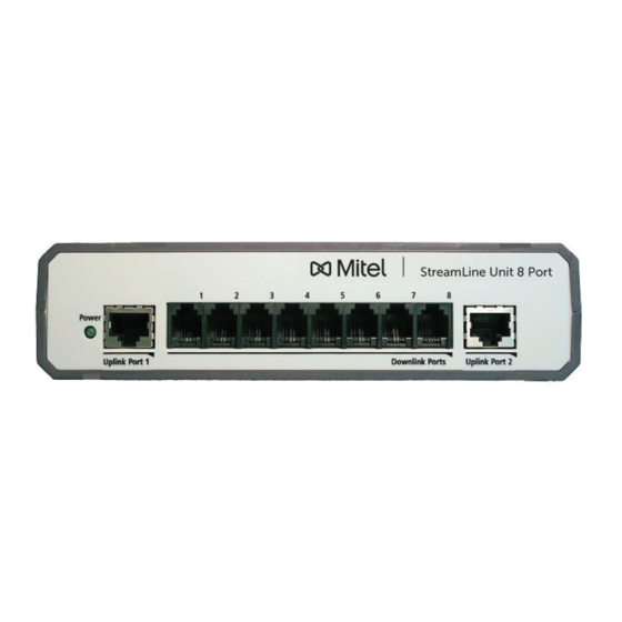
10/100 Mb/s Ethernet ports, Cat-5 cable should be used to make the connection to these ports. Uplink Port 1 is to be used to connect the StreamLine switch to the IP PBX, network switch or router. When more than 8 downlink ports are required a second StreamLine 8-Port switch can be added to expand the total downlink port count to 16 ports. - Page 22 Not Connected Note: Only one of the eight RJ11 is shown. StreamLine is supported on CAT-3 or better, and CW1308 cabling of up to 365 m (1,200ft). For more technical details, please consult the StreamLine Site Survey document available at "www.mitel.com/molstreamline".
-
Page 23: Rear View
StreamLine 8-Port The AC to DC power adapter provided by Mitel with the StreamLine 8-Port switch is the only approved power supply; DO NOT attempt to use any other power adapter. The AC to DC power adapter specifications are:... -
Page 24: Streamline Dongle Hardware Description
The StreamLine dongles are used with all the products in the StreamLine switch family. STREAMLINE DONGLE PRODUCT NUMBER The nameplate affixed to the bottom of the StreamLine Dongle enclosure indicates the product model number. You may be asked to provide this number if you contact Mitel Technical Support for assistance. Product Nameplate Location... -
Page 25: Streamline Dongle Dimensions
Speed: Fixed 10 Mb/s Full Duplex Auto-MDIX Cable: CAT-5 or better StreamLine is supported on CAT-3 or better, and CW1308 cabling of up to 365 m (1,200ft). For more technical details, please consult the StreamLine Site Survey document available at "www.mitel.com/molstreamline". - Page 26 Mitel StreamLine Switch - Hardware Installation Guide...
-
Page 27: Chapter 2 Unpacking Streamline Switches
PRODUCT PACKAGE When you first take the Mitel StreamLine 24-Port /48-Port switch out of its carton, lay out the unit and all of its accessories in your work area and verify that you have received all of the items you ordered. -
Page 28: Before You Install
PHYSICAL LOCATION REQUIREMENTS Power The Mitel StreamLine 24-Port/48-Port switch must be placed within 1.8 m (6ft) of an available AC power source. Do not use an extension cord to connect the equipment to a power outlet. Note: It is recommended that the Streamline Switch be powered from a dedicated power outlet. If... -
Page 29: Wiring Plant Requirements
Mitel StreamLine Switch - Hardware Installation Guide Downlink The StreamLine 24-Port/48-Port Dongles can be installed up to 365 m (1,200ft) away from the Mitel StreamLine switch. WIRING PLANT REQUIREMENTS A site survey and an examination of the existing wiring plant needs to be conducted prior to installing the StreamLine 24-Port/48-Port switch. - Page 30 Caution: If you plan to use two uplink connections, it is imperative that you enable the Rapid Spanning Tree Protocol (RSTP) and you consult with the Network Administrator to ensure that the network has been designed to support RSTP. Details on product configuration and management are provided in the Mitel StreamLine Administration Guide.
-
Page 31: Streamline 8-Port Switch
PRODUCT PACKAGE When you first take the Mitel StreamLine 8-Port switch out of its carton, lay out the unit and all of its accessories in your work area and verify that you have received all of the items you ordered. -
Page 32: Wiring Plant Requirements
10/100 Mb/s Ethernet ports; CAT-5 cable should be used to make the connection to these ports. Uplink Port 1 is to be used to connect the StreamLine switch to the IP PBX, network switch or router. When more than 8 downlink ports are required, a second StreamLine 8-Port switch can be added to expand the total downlink port count to 16 ports. -
Page 33: Installation
The following sections provide information related to installing the StreamLine 24-Port and 48-Port hardware. REQUIREMENTS Before you install the Mitel StreamLine, start it up or replace any components, review the suggestions in Chapter 2 Unpacking concerning: Size Requirements, page 20 ... -
Page 34: Safety Precautions
IP endpoint devices must be installed before you connect the Mitel StreamLine to a power source. CAUTION: To avoid possible damage to either the StreamLine switch or the IP end points, DO NOT POWER UP the StreamLine switch until all wiring has been completed and all IP end points are connected. -
Page 35: Care Of The Mitel Streamline 24-Port/48-Port Switches
Mitel StreamLine Switch - Hardware Installation Guide Attach the wrist strap cable to the ground lug at the rear of the Mitel StreamLine switch, identified with the Gnd symbol as shown below: Ground lug location at the rear of the Mitel StreamLine chassis. - Page 36 Mitel StreamLine (step 8). 4. Install a StreamLine Dongle on each IP phone, and plug the other end of the StreamLine Dongle into the RJ11 wall jack. See Replacing Legacy Devices with IP Endpoint Devices, page 32.
-
Page 37: Installing The Unit In A Rack
Unit using the 8 screws provided, for installation in a standard 48 cm (19”) rack. Note: No screws are supplied for mounting the Mitel StreamLine in the rack. You need a minimum of 4 screws for each rackmounted unit. Select the proper screw type and size for your equipment rack. - Page 38 To install the unit in a rack: 1. Attach the left rackmount bracket to the left side of the Mitel StreamLine switch near the front, using 4 of the screws provided. The rack ear should be flush with the front panel of the Mitel StreamLine.
-
Page 39: Rackmount Safety Instructions
Mitel StreamLine Switch - Hardware Installation Guide 3. Slide the Mitel StreamLine into the rack along its horizontal supports (or suspend the Unit in place using another means of support) so that the rackmount brackets at the front of the unit are in line with the vertical supports at the front of the rack, and at least 2 of the 3 holes in each rackmount bracket are aligned with holes on the rack. -
Page 40: Replacing Legacy Devices With Ip Endpoint Devices
1. Important: Remove all legacy analog/digital phones and fax machines from their Telco jacks (RJ11 wall plugs) before you carry out any further installation steps. 2. Connect the new IP phones to the StreamLine Dongles: Plug the IP phone to the RJ45 side of the StreamLine Dongle using a standard Ethernet cable. -
Page 41: Connecting A Pc Behind The Ip Phone
Note: Use a standard RJ21 Telco cable to connect the 2-wire network infrastructure to one of the downlink ports on the front panel of the Mitel StreamLine. The total cable length of the network infrastructure (from Mitel StreamLine to StreamLine Dongle) can be up to 365 m (1,200ft). -
Page 42: Connecting To The Console
3. Screw the cable connectors securely into place. CONNECTING TO THE CONSOLE The Mitel StreamLine Product Package includes a standard RJ45 to DB9 female console cable for connection to a console terminal or a computer running a terminal emulation program. -
Page 43: Connecting To The Ip Pbx
Mitel StreamLine Switch - Hardware Installation Guide CONNECTING TO THE IP PBX You can connect the Mitel StreamLine unit to the uplink network switch, IP PBX or router in two ways: GbE Port Connection (see next section) for copper LAN cable connection to either or both RJ45 ports labeled GbE 1 and GbE 2 on the front panel of the StreamLine switch. -
Page 44: Gbic Port Connection
The StreamLine switch supports 1000 Base-TX/SX/LX/EX/ZX/LHX, depending on which SFP transceiver module you install. The SFP transceivers are not a Mitel orderable part, SFP transceivers and fiber optic cabling are customer supplied items. -
Page 45: Installing The Sfp Transceiver Modules
Mitel StreamLine Switch - Hardware Installation Guide INSTALLING THE SFP TRANSCEIVER MODULES To install an SFP module: 1. Remove the SFP module from its protective packaging, but DO NOT remove the black protective cap. Small particles of dust can interfere with proper operation of the SFP module. -
Page 46: Installing The Fiber Optic Cable
Note: The SFP module cannot be removed from the port if its protective cap is on. INSTALLING THE FIBER OPTIC CABLE To connect the StreamLine unit to the uplink network switch or IP PBX using a fiber optic cable: 1. Remove the black protective cap from the SFP transceiver module. - Page 47 Mitel StreamLine Switch - Hardware Installation Guide 2. Connect your fiber optic cable to port GBIC 1 or GBIC 2 on the front panel of the StreamLine switch. Note: Both ports can be used. If only one connection will be installed, use the port labeled...
-
Page 48: Connecting To Power
StreamLine switch powered down, NEVER work on a cross-connect panel with live wires. The Mitel StreamLine is powered through an AC Connection (see next section). If more than one StreamLine switch is being installed, then the switches can be configured to support power supply redundancy. -
Page 49: Back Up Power
Consider deploying an Uninterruptable Power Supply (UPS) with sufficient capacity to power the StreamLine switches (and in turn the phones), the IP PBX, and any necessary L2 switches and routers for the length of time that the customer requires to maintain phone functionality during an AC power outage. -
Page 50: Multiple Unit Configurations
Mitel StreamLine Switch - Hardware Installation Guide MULTIPLE UNIT CONFIGURATIONS Multiple Mitel StreamLine units can be installed together in the same equipment rack for power and load sharing between multiple Mitel StreamLine units. A fully redundant ring can be created, providing redundant power to any unit that has a power failure. - Page 51 To daisy-chain multiple Mitel StreamLine Units for power supply redundancy: 1. Mount all Mitel StreamLine units in the same equipment rack, with no more than 1U space between any two units. Refer to Installing the Unit in a Rack Note: You can daisy-chain the units together while they are up and running or power them up afterward.
- Page 52 DC output (right) connector on the top unit. This is required to create a fully redundant ring. Note: If you need to move a cable to a different DC connector on the Mitel StreamLine, press the hairpin clip at the top of the DC cable and pull the cable out.
-
Page 53: Replacing The Power Supply Unit
PSU to replace the failed PSU. Spare PSUs, part number 50006601 can be purchased from Mitel Networks Corporation. Note: The power supply unit is removed and replaced from the front of the Mitel StreamLine switch. To remove the power supply unit: 1. - Page 54 2. Lift the new power supply unit by its handle, and slide it straight into the PSU housing on the left side of the Mitel StreamLine switch. 3. Push firmly on the power supply unit to insert its connector securely at the rear of the Mitel StreamLine.
-
Page 55: Streamline 8-Port Switch
PHYSICAL LOCATION REQUIREMENTS Power The Mitel StreamLine 8-Port switch must be placed within 1.8 m (6ft) of an available AC power source. Do not use an extension cord to connect the equipment to a power outlet. Note: It is recommended that the Streamline Switch be powered from a dedicated power outlet. If... -
Page 56: Uplink Ports
10/100 Mb/s Ethernet ports; CAT-5 cable should be used to make the connection to these ports. Uplink Port 1 is to be used to connect the StreamLine switch to the IP PBX, network switch or router. When more than 8 downlink ports are required, a second StreamLine 8-Port switch can be added to expand the total downlink port count to 16 ports. -
Page 57: Chapter 4 Technical Specifications
Mitel StreamLine Switch - Hardware Installation Guide Chapter 4 TECHNICAL SPECIFICATIONS MITEL STREAMLINE SWITCHES Table 1: Mitel StreamLine Model 24-Port and 48-Port Model Technical Specifications Description Specification 24-Port: Can drive up to 24 StreamLine Dongles Models 48-Port: Can drive up to 48 StreamLine Dongles... - Page 58 Mitel StreamLine Switch - Hardware Installation Guide Table 1: Mitel StreamLine Model 24-Port and 48-Port Model Technical Specifications Description Specification Power consumption Model 24-Port 16.5W (Does not Include PoE) Model 48-Port 22W DC voltage: -54VDC Power injection (PoE) Endpoint devices must be compliant with IEEE 802.3af...
- Page 59 -25°C to 70°C (-13°F to 158°F) Humidity 10% to 95% (non-condensing) at 35°C (95°F) StreamLine is supported on CAT-3 or better, and CW1308 cabling of up to 365 m (1,200ft). For more technical details, please consult the StreamLine Site Survey document available at "www.mitel.com/molstreamline".
- Page 60 1 RJ45 port: 10/100 Base-T, auto-sensing, Ethernet IEEE 802.3, used to provide connectivity to a second StreamLine 8-Port switch when more than 8 downlink ports are required. Connect this Port to Uplink Port 1 on the second StreamLine 8-Port Interface: Uplink Port 2 - switch.
-
Page 61: Mitel Wiring Harnesses
200-port wiring harness, 20 IDC strips with 200 ports wired and eight connector sockets. Wall mountable (hardware not included). 51300754 5m male to female system cable. Connects the StreamLine unit to the System Harness, Patch Panel, or other customer wiring solution. Two cables would be required for the StreamLine 48-port unit. - Page 62 Mitel StreamLine Switch - Hardware Installation Guide Terminal Block Pinouts (50-port Wiring Harness) K5 Color K4 Color Color K2 Color K1 Color 1A 16 Blue/Yellow 1A 6 Blue/Red 1A 21 Blue/Violet 1A 11 Blue/Black 1A 1 Blue/White 1B 41 Yellow/Blue ...
- Page 63 Mitel StreamLine Switch - Hardware Installation Guide...
-
Page 64: Appendix A Verifying Wiring And Cabling
Small Form Factor (SFF) GBIC sockets that can support two 1000 Base-T Small Form Factor Pluggable (SFP) fiber optic transceivers. These ports are used to connect the StreamLine 24-Port or 48-Port switches to the IP PBX. They carry an aggregate of all the data being carried by the downlink ports. -
Page 65: All Streamline Switches Downlink Ports
The StreamLine switches can provide a maximum of 10 watts of power to an IP end point (PD). This means that All IEEE 802.3af Class 1 and Class 2 devices and some Class 3 devices can be powered via PoE from the StreamLine switch. - Page 66 Mitel StreamLine Switch - Hardware Installation Guide tools can also check the cable for the presence of bridge taps. If bridge taps are detected, the tool will indicate how many feet or meters down the cable the bridge is located.
-
Page 67: Appendix B Acronyms And Abbreviations
Appendix B ACRONYMS AND ABBREVIATIONS ACRONYMS AND ABBREVIATIONS ACRONYM/ DEFINITION ABBREVIATION Alternating Current Command Line Interface Direct Current Graphical User Interface Internet Protocol IP Telephony Light Emitting Diode Network Management System OAM&P Operations, Administration, Maintenance and Provisioning Power over Ethernet Power Sourcing Equipment Power Supply Unit Random Access Memory... -
Page 68: Index
Mitel StreamLine Switch - Hardware Installation Guide INDEX 2-wire network infrastructure Environment, operating connection to operating environment, 5 2-wire network connection Front panel connection, 33 front view, 4 Acronyms, 59 Mitel StreamLine Audience, iii overview, 2 cable returning, iii CAT-5e copper, for GbE port, 35... - Page 69 Mitel StreamLine Switch - Hardware Installation Guide Powershare, 42 installation requirements, 24 removal SFP module, 38 Requirements distance, 47 replacement SFP module, 37 Ventilation requirements ventilation, 47 Downlink distance downlink distance, 21, 24, 47 Requirements installation Requirements requirements, 47 distance, 20...
- Page 70 © Copyright 2015, Mitel Networks Corporation. All Rights Reserved. The Mitel word and logo are trademarks of Mitel Networks Corporation. Any reference to third party trademarks are for reference only and Mitel makes no representation of the ownership of these marks.
Need help?
Do you have a question about the StreamLine and is the answer not in the manual?
Questions and answers