
Subscribe to Our Youtube Channel
Related Manuals for OXTS RT Series


Summary of Contents for OXTS RT Series
- Page 1 GNSS-aided inertial measurement systems User Manual Covers all RT models Confidently. Accurately.
- Page 2 Environmental protection Waste electrical products should not be disposed of with household waste. Please recycle where facilities exist. Check with your Local Authority or OxTS representative for recycling advice. Oxford Technical Solutions...
- Page 3 RT User Manual Copyright Notice The software is protected by copyright of Oxford Technical Solutions at oxts.com. © 2008–2019, Oxford Technical Solutions Ltd. Unauthorised use, copying or distribution is not permitted. The software also includes software in binary form from: Xiph.Org Foundation at xiph.org.
- Page 4 Revision Document Revision: 190130 (See Revision History for detailed information). Contact Details Oxford Technical Solutions Limited Tel: +44 (0) 1869 814 253 77 Heyford Park Upper Heyford Oxfordshire Web: http://www.oxts.com OX25 5HD Email: support@oxts.com United Kingdom Oxford Technical Solutions...
- Page 5 RT User Manual Warranty Oxford Technical Solutions Limited warrants its products to be free of defects in materials and workmanship, subject to the conditions set forth below, for a period of one year from the Date of Sale. ‘Date of Sale’ shall mean the date of the Oxford Technical Solutions Limited invoice issued on delivery of the product.
-
Page 6: Table Of Contents
Table of contents Introduction Easy operation Self-correcting Interchangeable Advanced processing Related documents RT product family Single antenna Dual antenna GLONASS 250 Hz Satellite differential corrections Scope of delivery RT2000 system components RT3000 system components RT4000 system components Specification Common specifications Notes on specifications Heading accuracy Environmental protection... - Page 7 Antenna placement and orientation Operation Front panel layout LED definitions Co-ordinate frame conventions IMU frame OxTS NED navigation frame ISO 8855 ENU earth-fixed system OxTS horizontal frame ISO 8855 intermediate system OxTS Vehicle frame ISO 8855 vehicle system Ethernet configuration...
- Page 8 Options Vehicle starts Vibration GNSS environment Differential correction SBAS DGNSS service Heading lock Garage mode Initialisation speed Displace output Distance output Analogue output Acceleration filter Wheel speed input Local co-ordinates Serial 1 output Ethernet output Steering robot IP Output smoothing Slip points GNSS control Surface tilt...
- Page 9 RT User Manual Using the orientation measurements Operating principles Internal components Strapdown navigator Kalman filter CAN messages and signals Termination resistor CAN-DB file CAN bus messages Table heading definitions Signals Revision history Drawing list Revision: 190204...
-
Page 10: Introduction
Introduction The RT family of inertial navigation system (INS) devices, are instruments for making precision measurements of motion in real-time. There are three divisions within the RT family; RT2000s, RT3000s and RT4000s—and each division contains a number of different models. The difference between the divisions is described in more detail in the “RT product family”... -
Page 11: Easy Operation
RT User Manual Internal data logging enables the data to be reprocessed post-mission. Data can be collected in the unit, downloaded using “ftp”, processed on a PC and viewed using the customer’s software. Easy operation There is minimal configuration required to use the system. The configuration can be saved to the RT so it can operate autonomously without user intervention. -
Page 12: Related Documents
NAVgraph is used to plot, analyse and export measurement data once processed Manual NCOM is a propriety format developed by OxTS that is used in our products. The NCOM Manual NCOM manual provides information about decoding and using the NCOM format... -
Page 13: Rt Product Family
RT User Manual RT product family The RT product family is split into three divisions—all based on similar technology, and within each division, there are a number of models serving different accuracy requirements. The RT family is split into the following divisions: •... -
Page 14: Glonass
The heading software in the RT enables significantly better performance and coverage compared to GNSS-only solutions. GLONASS GLONASS capability adds the ability to utilise the Russian satellite constellation GLONASS as well as the American constellation GPS. This means an extra 24 satellites are available for the RT to lock on to and obtain position and velocity updates from. - Page 15 RT User Manual these corrections. Capable RT system will use the TERRASTAR-D service which can provide better than 10 cm position accuracy. TerraStar is available on all continents. Marine versions also exist. For more information, see TerraStar’s web site: http://www.terrastar.net/. Revision: 190204...
-
Page 16: Scope Of Delivery
Scope of delivery RT products are supplied complete with cables, GNSS antennas, software and manuals. As standard, magnetic mount antennas are provided but other antenna types are available; please enquire for more details. RT2000 system components Table 2 lists all items that are delivered with each RT2000 model. Table 2. -
Page 17: Rt3000 System Components
RT User Manual RT3000 system components Table 3 lists all the items that are delivered with each RT3000 model. Table 3. Summary of RT3000 system components Description RT3100 RT3102 RT3100G RT3102G RT3002 RT3003 RT3002G RT3003G RT3000 system ... -
Page 18: Rt4000 System Components
RT4000 system components Table 4 lists all the items that are delivered with each RT4000 model. Table 4. Summary of RT4000 system components Description RT4100 RT4102 RT4100G RT4102G RT4002 RT4003 RT4002G RT4003G RT4000 system unit User cable ... - Page 19 RT User Manual Figure 1. Typical RT system and cables in transit case. Revision: 190204...
-
Page 20: Specification
Specification Specifications for RT products can be found in Table 5, Table 6, and Table 7. These specifications are listed for operation of the system under the following conditions: • After a warm-up period of 15 minutes’ continuous operation. • Open-sky environment, free from cover by trees, bridges, buildings or other obstructions. - Page 21 RT User Manual Position 3.0 m CEP 3.0 m CEP 1.5 m CEP 1.5 m CEP SPS accuracy 0.6 m CEP 2.0 m CEP 2.0 m CEP 0.6 m CEP SBAS SBAS SBAS SBAS 0.4 m CEP 0.5 m CEP 0.5 m CEP 0.4 m CEP DGPS...
- Page 22 Table 6. RT3000 / RT4000 v2 single antenna performance specification Parameter RT3100 v2/ RT3100G v2 / RT3002 v2 / RT3002G v2 / RT4100 v2 RT4100G v2 RT4002 v2 RT4002G v2 Positioning GPS L1 GPS L1 GPS L1, L2 GPS L1, L2 GLONASS L1 GLONASS L1, L2...
- Page 23 RT User Manual To achieve specification, relevant differential corrections from a base station, NTRIP or TerraStar subscription are required. The RTK accuracies are based on v2 products. 10-18 V dc voltage levels apply to units with the 14P009 front panel fitted, which was used prior to December 2011.
-
Page 24: Common Specifications
Dimensions 234 × 120 × 80 234 × 120 × 80 234 × 120 × 80 234 × 120 × 80 Mass 2.4 kg 2.4 kg 2.4 kg 2.4 kg To achieve specification, relevant differential corrections from a base station, NTRIP or TerraStar subscription are required. -
Page 25: Heading Accuracy
These safety standards will only apply when the RT2000 is used with the cables supplied or with the RT-UPS. Please note: if the equipment is used in a manner not specified by OxTS, the protection provided by the equipment may be impaired. - Page 26 Serial number ECCN RT2000 1–1422 7A003d RT2000 >=1423 Either 7A003d or 7A103a1, see invoice or delivery note or contact support at OxTS. Some products will have codes that relate to export control on their labels. EXCT-1—7A003d EXCT-2—7A103a1 RT3000, 1–799 7A003d RT4000 RT3000, >=800...
-
Page 27: Conformance Notices
ISO 7637-2 criterion B, 12 V according to standard EN 301 489-1:2008 (vehicular transients and surges immunity). Older RT systems do not conform to this standard, contact OxTS for further details. • RT3000/4000 products o 47 CFR 15.109:2010 class A (radiated emissions). - Page 28 o EN 61000-4 criterion A according to standard EN 301 489-1:2008 (-2:2009 electrostatic discharge), (-3:2006+A2:2010 radiated immunity), (-4:2012 electrical fast transients), (-5:2006 voltage surge) and (-6:2009 conducted radio frequency immunity). o EN 55022:2010 class A according to standard EN 301 489-1:2008 (Radiated electromagnetic emissions) and (conducted emissions).
-
Page 29: Software Installation
C:\Program Files (x86)\OxTS on 64 bit operating systems or C:\Program Files\OxTS on 32 bit operating systems. The first time some OxTS applications are run, a firewall warning message similar to that shown in Figure 2 may be triggered. This is because the program is attempting to listen for, and communicate with, OxTS devices on the network. - Page 30 configured to allow each program to talk on the network, or programs will not work as intended. Figure 2. Windows Firewall warning message Ensure both Private and Public networks are selected to ensure the software can continue functioning when moving from one type to another. Oxford Technical Solutions...
-
Page 31: Hardware Installation
In most circumstances the RT should be mounted directly to the chassis of the vehicle. If the vehicle experiences high shocks, then vibration mounts may be required. The RT is compatible with the RT-Strut product from OxTS to provide a quick and secure vehicle mounting solution. - Page 32 then different antennas must be used. It is recommended to mount the antennas at least 30 cm from any edge where possible. For dual antenna systems, the secondary antenna should be mounted in the same orientation as the primary antenna, as shown in Figure 3. The antenna baseline should also be aligned with one of the vehicle axes where possible, either inline or perpendicular to the vehicle’s forward axis.
-
Page 33: Operation
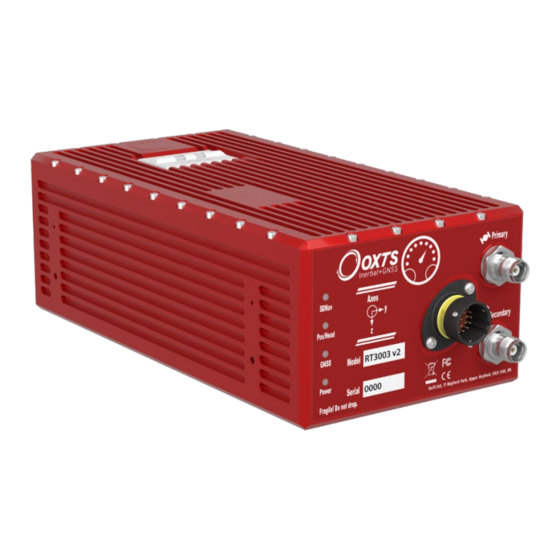
RT User Manual Operation The front panel label and LEDs convey some basic information that aid configuration and troubleshooting. Once power is applied, the RT requires no further input from the user to start logging and outputting data. This section covers some basic information required for operation of the RT. Front panel layout Figure 4 and Figure 5 show the layouts of the RT front panels. - Page 34 Primary antenna connector Secondary antenna connector M12 power connector Ethernet port Figure 5. RT3000/RT4000 front panel layout Table 12. RT3000/RT4000 front panel descriptions Label no. Description SDNav LED Position LED (single antenna systems) Heading LED (dual antenna systems) GPS LED Power LED Primary antenna connector User cable main connector...
-
Page 35: Led Definitions
The operating system has not yet booted and the program is not yet running. This occurs at start-up. Red-green flash The RT is asleep. Contact OxTS support for further information. Red flash The operating system has booted and the program is running. The GNSS receiver has not yet output a valid time, position, or velocity. - Page 36 Green The GNSS receiver has an integer (good) calibrated heading lock. Table 18. GPS LED states Colour Description Green flash The GNSS receiver is functioning normally. Other The GNSS receiver has failed. Contact OxTS for further information. Oxford Technical Solutions...
-
Page 37: Co-Ordinate Frame Conventions
RT User Manual Table 19. Power or Pwr LED states Colour Description There is no power to the system or the system power supply has failed. Green The 5 V power supply for the system is active. Orange The system is outputting data on connector J2. Co-ordinate frame conventions Measurements made by the INS are available in a number of different reference frames for use in different applications. - Page 38 Figure 6. IMU co-ordinate frame and measurement origin Table 20 lists the directions that the axes should point for zero heading, pitch and roll outputs when the default mounting orientation is used. Table 20. Direction of axes for zero heading, pitch and roll outputs Axis Direction Vehicle axis...
-
Page 39: Oxts Ned Navigation Frame
The down axis (D) is along the gravity vector. Figure 7. OxTS NED navigation frame definition The OxTS navigation frame is attached to the vehicle but does not rotate with it. The Down axis is always aligned to the gravity vector and North always points North. -
Page 40: Oxts Horizontal Frame
The OxTS horizontal frame (sometimes called the level frame) is attached to the vehicle but does not rotate with the roll and pitch of the vehicle. It rotates by the heading of the vehicle. The definition of the OxTS Horizontal frame is listed in Table 23 and shown in Figure 9. -
Page 41: Iso 8855 Intermediate System
Figure 9. OxTS horizontal frame definition The OxTS horizontal frame is attached to the vehicle. The longitudinal and lateral axes remain parallel to a horizontal plane. The Longitudinal axis is also parallel to the vehicle’s heading when viewed from above. -
Page 42: Oxts Vehicle Frame
Figure 11. Vehicle frame definition The OxTS vehicle frame is attached to the vehicle and rotates with it in all three axes. The X-axis remains parallel to the vehicle’s heading, while the Y-axis points to the right and is perpendicular to the vehicle’s... -
Page 43: Iso 8855 Vehicle System
RT User Manual ISO 8855 vehicle system The ISO 8855 vehicle system is attached to the body of the vehicle. At rest, the X-axis points forwards horizontally and is parallel to the vehicle’s longitudinal axis. The Y-axis is perpendicular to the longitudinal axis and points left. The Z-axis is orthogonal to the X- and Y-axes. - Page 44 The RT outputs its data over Ethernet using a UDP broadcast. The use of a UDP broadcast allows everyone on the network to receive the data sent by the RT. The data rate of the UDP broadcast is 100 Hz or 250 Hz depending on the RT model. In order to communicate via Ethernet, each RT is configured with a static IP address that is shown on the delivery note.
-
Page 45: Connection Details
RT User Manual Figure 13. Configuring the computer's IP address Once the computer is configured the IP address of a RT can be found by running NAVdisplay software; this will display the IP address of any RT connected. Note that it is possible to change the IP address of RT systems. If the IP address has been changed then NAVdisplay should still be able to identify the address that the RT is using as long as the PC has a valid IP address and this is not the same as the RT’s. -
Page 46: Dual Antenna Systems
Table 27. In-line coupler connections Socket 1 Straight socket 2 Crossed socket 2 Pin 1 Pin 1 Pin 6 Pin 2 Pin 2 Pin 3 Pin 3 Pin 3 Pin 2 Pin 4 Pin 4 – Pin 5 Pin 5 –... - Page 47 RT User Manual If the RT is mounted in the vehicle with a large heading offset then the initial value of heading will be incorrect. This can also happen if the RT is initialised in a turn. This can lead to problems later. When the combined accuracy of heading plus the orientation accuracy figure for the secondary antenna is sufficiently accurate then the RT will solve the RTK Integer problem using the inertial heading.
-
Page 48: Multipath Effects On Dual Antenna Systems
Multipath effects on dual antenna systems Dual antenna systems are very susceptible to the errors caused by multipath. This can be from buildings, trees, roof-bars, etc. Multipath is where the signal from the satellite has a direct path and one or more reflected paths. Because the reflected paths are not the same length as the direct path, the GNSS receiver cannot track the satellite signal as accurately. -
Page 49: Inputs And Outputs
RT is a proprietary binary format, referred to as NCOM. OxTS offers C and C++ code that will interpret the packet. This can be used freely in users’ programs to interpret the output of the RT. More information about NCOM can be found in the NCOM description manual. -
Page 50: 1Pps Output
Digital ground Reserved 1PPS output The 1PPS output is a pulse from the GNSS receiver. The falling edge of the pulse is the exact transition from one second to the next in GPS time. The pulse is low for 1 ms, then high for 999 ms and repeats every second. -
Page 51: Wheel Speed Input
RT User Manual Wheel speed input The wheel speed input accepts TTL pulses from an encoder on a single wheel. An encoder from a gearbox should not be used, and simulated TTL pulses (e.g. from the CAN bus) should not be used. The timing of the wheel speed input pulses is critical and nothing should cause any delay in the wheel speed input pulses. - Page 52 appropriate five amp, fast-blow fuse should be fitted and the safety specification will no longer apply. RT3000 and RT4000 products have not had a formal safety test. If the fuse in the plug needs to be replaced, then it should be replaced with the Littelfuse model given in Table 30 below.
-
Page 53: Configuring The Rt
RT User Manual Configuring the RT To obtain the best results from your RT it will be necessary to configure the RT to suit the installation and application before using it for the first time. The program NAVconfig can be used to do this. This section describes how to use NAVconfig and gives additional explanations on the meanings of some of the terms used. -
Page 54: Selecting The Operating Language
Selecting the operating language The NAVconfig software can operate in several languages. To change the language, select a language from the menu at the bottom of the page. The language can be changed at any time without affecting the current configuration. NAVconfig uses the regional settings of the computer to choose whether numbers are represented in the English or European format (dot or comma for the decimal separator). -
Page 55: Reading Configuration
The product model and generation can be found on the connector panel of your product. If you only own one type of OxTS product, the Product Selection page can be skipped in the future by clicking the Always use this product checkbox. If a different product needs configuring, the selection page can be returned to by clicking Product Selection in the sidebar. - Page 56 Figure 17. NAVconfig Read Configuration page Use default settings: NAVconfig loads the default settings the RT was delivered with. Note: choosing Use default settings overwrites any advance settings that may have been sent with prior configurations. To maintain those advanced settings, the Read initial settings from device option must be used.
-
Page 57: Gnss Selection
Note: the list will not function correctly if NAVdisplay or other software is using the RT UDP port unless the OxTS UDP Server is running. - Page 58 Use the Y axis points and the Z axis points box to specify which way the RT’s axes point in the vehicle. Figure 6 on page 38 shows the RT axes directions. The Orientation page of the configuration wizard, shown in Figure 19, also has illustrations to visualise the orientation of the RT in a vehicle based on the settings input.
-
Page 59: Get Improved Settings
RT User Manual Get improved settings The Get improved settings button provides the ability to read the configuration settings from a warmed up system. While the RT is running it tries to improve some of its configured parameters. This option is useful if a calibration run has been done and the Kalman filter’s values are known to be good. - Page 60 Select the correct IP address of the RT to read the configuration from in the drop-down list. Note: the list will not function correctly if NAVdisplay or other software is using the RT UDP port unless the OxTS UDP Server is running Once the source has been selected, click Next and the software will find which settings can be obtained from the source.
-
Page 61: Primary Antenna
RT User Manual Figure 22. Select which settings to update with Get improved settings If Orientation in vehicle is selected, the improvement to orientation should only be applied if the change in the orientation is small (less than 5°). If the change in orientation is large then it is likely that the original configuration was wrong or has not been loaded into NAVconfig. - Page 62 Figure 23. NAVconfig Primary Antenna page It is necessary to tell the RT the distance between its measurement origin (shown in Figure 6) and the GNSS antenna’s measurement point. This should be entered in the vehicle’s co-ordinate frame. The accuracy of the measurements should also be specified, and care should be taken here.
-
Page 63: Secondary Antenna
RT User Manual Secondary antenna If your system has dual antennas, click the Enable secondary antenna checkbox on the Secondary Antenna page (Figure 24) to allow the configuration to be entered. If it is not enabled, the RT will ignore the secondary antenna and will not use it to compute a heading solution. -
Page 64: Advanced Slip
Getting the angle wrong by more than 3° can lead the RT to lock on to the wrong heading solution. The performance will degrade or be erratic if this happens. If the angle between the antennas cannot be estimated within a 3° tolerance then contact OxTS support for techniques for identifying the angle of the antennas. - Page 65 RT User Manual speed input (see “Wheel speed input” on page 81) the drift of the RT when GNSS is not available is drastically reduced. Figure 25 shows the Advanced Slip page of NAVconfig. Figure 25. NAVconfig Advanced Slip page For the Lateral settings, the system needs to know the position of the non-steered axle (rear wheels on a front-wheel steering vehicle and vice versa).
-
Page 66: Options
Figure 26. Measurement point for Advanced slip Measuring from the RT, measure the distances to the non-steered axle position in each axis in the vehicle co-ordinate frame. Select the direction from the drop-down lists and enter the distances. Typically the measurements would all be made to an accuracy of 10 cm. Selecting an accuracy better than 10 cm does not improve results. -
Page 67: Vehicle Starts
RT User Manual To adjust the settings, click the default value in the Setting column to activate the cell. A description on each option and how to adjust it is found below. Clicking in either column header will sort the Options in ascending or descending alphabetical order. Figure 27. -
Page 68: Gnss Environment
The Normal vibration level is adequate for most circumstances. The RT is very tolerant of vibration and has been used successfully in environments with more than 2 g RMS using the Normal setting. If the velocity innovations are very high, and many GNSS packets are being dropped, then this setting can be changed. - Page 69 RTCM is the most common open standard used for differential corrections. Old implementations of RTCM did not support 1 cm corrections, which is why OxTS uses RTCA by default. New versions of the RT products support 1 cm corrections over RTCM.
-
Page 70: Sbas
RT will broadcast differential corrections it is receiving via a radio modem from an OxTS base station, using its RT-XLAN. Other RT devices that are on the network as the broadcasting RT, will then be able to receive the DGPS messages and use them. -
Page 71: Can
RT User Manual Several satellites have been pre-programmed into the software. In the future more satellites may exist, or their properties may change. In this case it is necessary to select Use advanced settings to set the satellite’s Frequency and Baud rate. Adjustment: click …... - Page 72 reducing the frequency of navigation or status messages will remove the warning and ensure reliable operation of the CAN bus. Increasing the baud also works, but the baud rate must be common to all devices on the bus. When using an RT-ANA, the default baud rate is 1 MBaud.
- Page 73 RT User Manual Figure 30. NAVconfig CAN messages configuration window - Navigation The Prefix and Postfix boxes can be used to quickly add alpha-numeric strings to the beginning or end of all message names. By clearing the prefix or postfix, and then clicking the Apply button, the original message name will be restored.
- Page 74 the bottom of the window displaying messages per second updates to reflect the new settings. The Enable all button quickly enables all messages. The Disable all button disables all messages. On RT4000 systems the default set of CAN messages may overload the CAN bus (depending on how many slip points are used and whether local co-ordinates are configured).
- Page 75 RT User Manual Figure 31. NAVconfig CAN messages configuration window - Status The Acquisition tab (Figure 32) is where incoming CAN signals are defined. These signals can be viewed in real-time along with the RT’s native data using NAVdisplay, or at a later time using NAVgraph.
- Page 76 Figure 32. NAVconfig CAN messages configuration window - Acquisition The Message name, Signal name and Units can be edited in the CAN Signal Properties window (Figure 33). This is opened by double-clicking any signal. Changes made using NAVconfig are independent of the DBC file, and will not affect it or be saved. Oxford Technical Solutions...
-
Page 77: Heading Lock
RT User Manual Figure 33. NAVconfig CAN signal properties window Heading lock Adjustment: select a predefined value from the drop down list. The heading of single antenna systems can drift when the RT remains stationary for long periods of time. To solve this, the RT includes an option to lock the heading to a fixed value when stationary. -
Page 78: Garage Mode
Very tight The option assumes the heading of the vehicle does not change by more than 0.3° while the vehicle is stationary. The recovery is fast if the heading of the vehicle does not change but will be slow if the vehicle turns before it moves. This option can cause problems during the warm-up period if the vehicle remains stationary for a long time and then drives suddenly. -
Page 79: Distance Output
RT User Manual To enable output displacement, click the checkbox in the properties window and enter the offsets to the new location in the vehicle. The offsets are measured from the RT in the vehicle co-ordinate frame. Select the directions from the drop-down lists. Note that the noise in the acceleration outputs will be much higher when output displacement is used. -
Page 80: Acceleration Filter
These filters affect the outputs on the CAN bus. On the NCOM output the non-filtered values are output together with the filter characteristics and the NCOM decoders provided by OxTS will implement the chosen filter. The linear acceleration and the angular acceleration can be configured separately. -
Page 81: Wheel Speed Input
RT User Manual Designing the right filter is always a compromise between the noise reduction and the filter delay. To help choose the filter, the software will compute the maximum delay over the 0 to 5 Hz interval and the Noise Reduction Factor over the full bandwidth. The Noise Reduction Factor is the ratio of the filtered noise compared to the unfiltered noise assuming the vibration is white (i.e. - Page 82 As with the Advanced slip feature, the wheel speed input can only be used on land vehicles; aircraft and marine vehicles cannot use this option. The wheel speed must not be used on a steered wheel, it must be used on a wheel that is measuring the forward direction of the vehicle.
-
Page 83: Local Co-Ordinates
RT User Manual window will change depending on the settings you choose, to help visualise the position of the RT in relation the wheel speed. Ideally the measurements would be made to an accuracy of 10 cm. Using higher precision for the measurement does not improve the results. -
Page 84: Serial 1 Output
Figure 37. NAVconfig local co-ordinate properties window Serial 1 output Adjustment: click … button to open properties window. The serial output ports can be configured for different message types. Figure 38 shows the properties windows for the Serial 1 output. Oxford Technical Solutions... - Page 85 RT User Manual Figure 38. NAVconfig serial 1 output properties window Note: NMEA tab only appears when NMEA is selected from the Packet drop-down list. Select the message type to output from the Packet drop-down list and select the baud rate and data rate to output at.
-
Page 86: Ethernet Output
Javad I+RTK A special set of messages output in GREIS format to be used with Javad receivers. For assistance please contact OxTS for support. MCOM Used for marine applications. Identical to NCOM output but with the addition of heave measurements. - Page 87 This mode is enabled automatically by selecting a distance output of less than 1 ppm—contact support@oxts.com for details. These messages are interpolated to the time when the event occurred and may be output up to 30 ms late and out of order compared to the normal messages.
-
Page 88: Steering Robot Ip
Steering robot IP Adjustment: select a predefined value from the drop down list, or type in a value. The default address (195.0.0.100) is listed in the drop-down list but can be changed if required by typing the correct address. When the ABD Steering Robot is enabled, the output smoothing is automatically enabled too. -
Page 89: Slip Points
RT User Manual If a large error is accumulated (for example, if GNSS is not available for a long period of time) then it may take a very long time to apply the correction. Under these circumstances it may be preferable to “jump” the measurement to the correct value quickly. -
Page 90: Gnss Control
Figure 41. NAVconfig Slip points properties window GNSS control Adjustment: click … button to open properties window. The GNSS control option contains advanced options that control how the GNSS information is managed in the RT. The GNSS Algorithm tab can be used to select the algorithm used for merging the GNSS and the inertial data in the Kalman filter. - Page 91 RT User Manual Figure 42. NAVconfig GNSS control properties window The GNSS algorithm tab gives a choice of two algorithms for computing the GNSS measurements. The default option is to use the algorithm provided by the GNSS receiver. Using this algorithm the RT will accept position and velocity from the GNSS and use it to update the Kalman filter.
-
Page 92: Surface Tilt
GLONASS Note: only RTCM V3 format differential corrections are supported in gx/ix mode. The Recovery tab controls how the RT will accept or reject GNSS measurements. The RT will automatically reject GNSS updates that it believes are not correct. However, there is a limit on the number of GNSS measurements the RT will reject. -
Page 93: Coordinate System
RT User Manual angles. NAVconfig can be used to configure the surface’s angle if it has been measured already. Figure 43 shows the Surface tilt properties window. Figure 43. NAVconfig Surface tilt properties window Enter the heading (compared to true north) of the uphill direction and the gradient of the surface. -
Page 94: Advanced
C:\Users\username\Documents\OXTS\Shared\Custom geoid files. Once the file is downloaded and saved in this location, it can be selected from the dropdown box. A constant offset to the specified altitude reference can be applied by checking the Set offset box typing in a value into the cell. -
Page 95: Committing The Configuration To The Rt
The drop-down box will list all systems currently connected to the computer’s network so ensure to select the correct system if there are multiple listed. The list will not function correctly if NAVdisplay or other software is using the RT UDP port unless the OxTS UDP server is running. -
Page 96: Saving The Configuration And Finishing
Press Commit to save the configuration in the RT. This will automatically reset the RT so the changes take effect. It will be necessary to initialise and warm-up the RT again after the changes have been applied. Saving the configuration and finishing Before finishing it is possible to save a copy of the configuration in a folder on the computer. -
Page 97: Setting Up The Base Station
RT User Manual Setting up the base station For correct operation of the higher accuracy systems it is necessary to use a base station GNSS receiver. All of the systems can be successfully used without a base station, however, the specification will only be met if a base station is used. The base station is a separate GNSS receiver that monitors signals from the GNSS satellites. -
Page 98: Initialisation Process
Initialisation process Before the RT can start to output all the navigation measurements, it needs to initialise itself. In order to initialise, the RT needs all the measurements listed in Table 36. Table 36. Quantities required for initialisation Quantity Description Time Measured by internal GNSS. -
Page 99: Warm-Up Period
RT User Manual Warm-up period During the first 15 minutes of operation the system will not conform to specification. During this period the Kalman Filter runs a more relaxed model for the sensors. By running a more relaxed model the system is able to: 3. - Page 100 Figure 47. Example warm-up driving route At the start there is just a small amount of motion to get the RT3003 initialised. During this time the Kalman filter cannot improve the position accuracy because the position of the GNSS antenna is not known accurately and cannot be estimated without motion. The accuracy of the velocity, roll and pitch steadily improves as the Kalman filter places more and more weight on the inertial sensors.
- Page 101 RT User Manual Figure 48. Example warm-up accuracy estimates (a) Forward velocity. (b) Position accuracies. (c) Velocity accuracies. (d) Orientation accuracies. Revision: 190204...
- Page 102 You can see the RT3003 is nearly at specification after just this small amount of driving. However, experience tells us the Kalman filter will continue to make some improvements (not obvious) during the first few figures of eight. The main part of the motion occurs after 1100 s when the car was driven in a figure of eight for 6 minutes.
-
Page 103: Post-Processing Data
NAVsolve also gives the user the ability to change the NCOM binary output format to text. A full explanation of NAVsolve is given in the “NAVsolve Manual”, which can be downloaded from the OxTS support website. Revision: 190204... -
Page 104: Laboratory Testing
Laboratory testing There are several checks that can be performed in the laboratory to ensure the system is working correctly. The most fragile items in the system are the accelerometers, the other items are not subject to shock and do not need to be tested as thoroughly. Accelerometer test procedure To check the accelerometers are working correctly, follow this procedure. - Page 105 It is hard to do a more exhaustive test using the angular rate sensors without specialised software and equipment. For further calibration testing it is necessary to return the unit to OxTS. Note that the RT is capable of correcting the error in the angular rate sensors very accurately.
-
Page 106: Testing The Internal Gnss And Other Circuitry
Testing the internal GNSS and other circuitry To check all the internal circuits in the RT are working correctly and the navigation computer has booted correctly, use the following procedure: Connect power to the system, connect the system to a laptop computer and run the visual display software (NAVdisplay). -
Page 107: Using The Orientation Measurements
RT User Manual Using the orientation measurements This section has been provided to clarify the definitions of heading, pitch and roll that are output by the RT. The RT uses quaternions internally to avoid the problems of singularities and to minimise numerical drift on the attitude integration. -
Page 108: Operating Principles
Operating principles This short section gives some background information on the components in the RT and how they work together to give the outputs. A short overview of the algorithm is given and some explanation of how the software works. The section is provided as ‘interesting information’... -
Page 109: Strapdown Navigator
RT User Manual The sampling process in the inertial measurement unit is synchronised to GPS time so the 100 Hz or 250 Hz measurements from the RT are synchronised to GPS. The navigation computer is a Pentium class processor that runs the navigation algorithms (more on this below). -
Page 110: Kalman Filter
Some other rotations are also missed in the diagram. The RT does not use a wander angle, so it will not operate correctly on the North and South poles. The angular rates have their bias and scale factor corrections (from the Kalman filter) applied. - Page 111 RT User Manual The same principles are used in the RT. Position and velocity are compensated directly, but other measurements like accelerometer bias, have no direct measurements. The Kalman filter tunes these so the GNSS measurements and the inertial measurements match each other as closely as possible.
-
Page 112: Can Messages And Signals
OxTS NED frame velocity Table 44 1540 (604h) VelocityLevel OxTS horizontal frame velocity Table 45 1541 (605h) AccelVehicle OxTS output frame IMU acceleration Table 46 1542 (606h) AccelLevel OxTS horizontal frame IMU acceleration Table 47 1543 (607h) HeadingPitchRoll OxTS orientation... - Page 113 RT User Manual 1544 (608h) RateVehicle OxTS output frame IMU angular rate Table 49 1545 (609h) RateLevel OxTS horizontal frame IMU angular rate Table 50 1546 (60Ah) TrackSlipCurvature Track, slip and curvature Table 51 1547 (60Bh) Distance Distance Table 52...
- Page 114 1587 (633h) IsoOrientation ISO 8855 orientation Table 73 1588 (634h) IsoVsVelocity ISO 8855 vehicle system velocity Table 74 1589 (635h) IsoVsAcceleration ISO 8855 vehicle system acceleration Table 75 1590 (636h) IsoVsAngularVelocity ISO 8855 vehicle system angular velocity Table 76 ISO 8855 vehicle system angular 1591 (637h) IsoVsAngularAcceleration Table 77...
-
Page 115: Signals
RT User Manual Signals The following tables describe the signals in each of the messages. Table 41. Identifier 600h (1536), DateTime Description Signal name Year within century Year (e.g. ‘16’ during year TimeYear 2016) Century (e.g. ‘20’ Year TimeCentury during 2016) Month Month TimeMonth... - Page 116 Table 44. Identifier 603h (1539), Velocity Description Signal name OxTS NED frame 0.01 VelNorth north velocity OxTS NED frame east 0.01 VelEast velocity OxTS NED frame 0.01 vertical (down) VelDown velocity 0.01 Horizontal speed Speed2D The horizontal speed is the vector addition of north and east velocities. For forward speed (which can go negative) see message 604h.
- Page 117 RT User Manual Table 47. Identifier 606h (1542), AccelLevel Description Signal name OxTS horizontal frame 0.01 longitudinal (forward) AccelForward IMU acceleration OxTS horizontal frame 0.01 lateral (right) IMU AccelLateral acceleration OxTS horizontal frame 0.01 vertical (down) IMU AccelDown acceleration 0.01...
- Page 118 Table 50. Identifier 609h (1545), RateLevel Description Signal name OxTS horizontal frame °/s 0.01 longitudinal (forward) AngRateForward IMU angular rate OxTS horizontal frame °/s 0.01 lateral (right) IMU AngRateLateral angular rate OxTS horizontal frame °/s 0.01 vertical (down) IMU AngRateDown angular rate See message 608h for roll angular rate.
- Page 119 Note: The convention used for the local co-ordinates uses a right-handed set with the z-axis up. Table 55. Identifier 60Eh (1550), AngAccelVehicle Description Signal name °/s² OxTS output frame longitudinal (forward) AngAccelX IMU angular acceleration °/s² OxTS output frame...
- Page 120 Table 56. Identifier 60Fh (1551), AngAccelLevel Description Signal name °/s² OxTS horizontal frame longitudinal (forward) AngAccelForward IMU angular acceleration °/s² OxTS horizontal frame lateral (right) IMU AngAccelLateral angular acceleration °/s OxTS horizontal frame vertical (down) IMU AngAccelDown angular acceleration Table 57. Identifier 620h (1568), TrackSlipCurvaturePoint1...
- Page 121 RT User Manual Table 59. Identifier 622h (1570), TrackSlipCurvaturePoint3 Description Signal name ° 0.01 Measurement point 3 AngleTrackPoint3 track angle ° 0.01 Measurement point 3 AngleSlipPoint3 slip angle 0.0001 Measurement point 3 CurvaturePoint3 curvature Note that the slip angle of point 3 will be close to 180° when driving backwards. Table 60.
- Page 122 Table 62. Identifier 625h (1573), TrackSlipCurvaturePoint5 Description Signal name ° 0.01 Measurement point 5 AngleTrackPoint5 track angle Measurement point 5 ° 0.01 AngleSlipPoint5 slip angle 0.0001 Measurement point 5 CurvaturePoint5 curvature Note that the slip angle of point 5 will be close to 180° when driving backwards. Table 63.
- Page 123 RT User Manual Table 65. Identifier 628h (1576), TrackSlipCurvaturePoint8 Description Signal name ° 0.01 Measurement point 8 AngleTrackPoint8 track angle ° 0.01 Measurement point 8 AngleSlipPoint8 slip angle 0.0001 Measurement point 8 CurvaturePoint8 curvature Note that the slip angle of point 8 will be close to 180° when driving backwards. Table 66.
- Page 124 Table 68. Identifier 62Bh (1579), ApproxVelocity Description Signal name Approximate OxTS 0.01 NED frame north ApproxVelNorth velocity Approximate OxTS 0.01 NED frame east ApproxVelEast velocity Approximate OxTS 0.01 NED frame vertical ApproxVelDown (down) velocity Approximate 0.01 ApproxSpeed2D horizontal speed Before initialisation the approximate velocity message will have the GNSS measurement of velocity (at the GNSS antenna location).
- Page 125 RT User Manual Trigger count, increments with each TriggerCountRising new trigger 0.0002 Time since last trigger TriggerTimeRising Distance with hold 0.001 TriggerDistanceRising since last trigger Table 71. Identifier 62Fh (1583), PosLocalNE Description Signal name 0.0001 Northing PosLocalNorth 0.0001 Easting PosLocalEast Table 72.
- Page 126 ° 0.01 ISO 8855 pitch angle IsoPitchAngle ° 0.01 ISO 8855 roll angle IsoRollAngle Table 74. Identifier 634h (1588), IsoVsVelocity Description Signal name ISO 8855 vehicle 0.01 system longitudinal IsoVsLongitudinalVelocity (forward) velocity ISO 8855 vehicle 0.01 system lateral (left) IsoVsLateralVelocity velocity ISO 8855 vehicle 0.01...
- Page 127 RT User Manual Table 76. Identifier 636h (1590), IsoVsAgularVelocity Description Signal name ISO 8855 vehicle system roll °/s 0.01 IsoVsRollVelocity (longitudinal angular) velocity ISO 8855 vehicle °/s 0.01 system pitch (lateral IsoVsPitchVelocity angular) velocity ISO 8855 vehicle °/s 0.01 system yaw (vertical IsoVsYawVelocity angular) velocity Table 77.
- Page 128 ISO 8855 intermediate 0.01 IsoIsLateralVelocity system lateral (left) velocity ISO 8855 intermediate 0.01 IsoIsVerticalVelocity system vertical (up) velocity Table 79. Identifier 639h (1593), IsoIsAcceleration Description Signal name ISO 8855 intermediate system m/s² 0.01 IsoIsLongitudinalAcceleration longitudinal (forward) acceleration ISO 8855 intermediate m/s²...
- Page 129 RT User Manual ISO 8855 intermediate °/s 0.01 system pitch IsoIsPitchVelocity (lateral angular) velocity ISO 8855 intermediate °/s 0.01 system yaw IsoIsYawVelocity (vertical angular) velocity Table 81. Identifier 63Bh (1595), IsoIsAngularAcceleration Description Signal name ISO 8855 intermediate system roll °/s² IsoIsRollAcceleration (longitudinal angular)
- Page 130 ISO 8855 earth- 0.01 fixed system IsoEfsNorthVelocity north velocity ISO 8855 earth- fixed system 0.01 IsoEfsVerticalVelocity vertical (up) velocity Table 83. Identifier 63Dh (1597), IsoEfsAcceleration Description Signal name ISO 8855 earth- fixed system m/s² 0.01 IsoEfsEastAcceleration east acceleration ISO 8855 earth- fixed system m/s²...
-
Page 131: Revision History
RT User Manual Revision history Table 84. Revision history Revision Comments 071120 Merged RT2000, RT3000 and RT4000 manuals. 080121 Heading Lock changes. Surface Attitude CAN IDs. 080303 Improved RT2500 specification. Heading Lock “Loose” changed to “Normal”. Surface tilt added to RT Config. Specification changes for “1σ”. Clarified positioning 080804 modes and accuracies. -
Page 132: Drawing List
Drawing list Table 85 lists the available drawings that describe components of the RT system. Many of these drawings are attached to the back of this manual. Note that the ‘x’ following a drawing number is the revision code for the part. If you require a drawing, or different revision of a drawing, that is not here then contact Oxford Technical Solutions.
Need help?
Do you have a question about the RT Series and is the answer not in the manual?
Questions and answers