Table of Contents
Advertisement
Quick Links
Advertisement
Table of Contents

Related Manuals for OXTS AV200


Summary of Contents for OXTS AV200
- Page 1 Hardware Integration Manual AV200...
-
Page 2: Legal Notices
Contact details Oxford Technical Solutions Limited Park Farm Business Centre Middleton Stoney Oxfordshire OX25 4AL United Kingdom Tel: +44 (0) 1869 814 253 Fax: +44 (0) 1869 251 764 Web: http://www.oxts.com Email: support@oxts.com Oxford Technical Solutions Ltd www.oxts.com Page 2 of 26... -
Page 3: Warranty And Liability
The user is responsible for conducting a proper risk assessment when integrating the product. Please contact OxTS if you believe any service or repair is required on your product. It is possible to connect the product to a vehicle CAN bus for gathering data, in which case there is potential to influence the behaviour of electronic control units. -
Page 4: Table Of Contents
List of figures Figure 1: AV200 front view ........................9 Figure 2: AV200 top view ........................10 Figure 3: AV200 dimensions and measurement origin point (mm)............11 Figure 4: AV200 coordinate frame axes ....................13 Oxford Technical Solutions Ltd www.oxts.com... - Page 5 Figure 5: AV200 main connector pin layout ..................14 Figure 6: PPS waveform ........................15 Figure 7: AV200 user cable........................15 Figure 8: AV200 mounting points (mm) ....................17 Figure 9: Dual antenna orientation ......................18 List of tables Table 1: Supplementary manuals ......................6 Table 2: AV200 scope of delivery ......................
-
Page 6: Introduction
Related documents This manual covers the installation and operation of the AV200, but it is beyond its scope to provide details on service or repair. Contact OxTS support or your local representative for customer service- related enquiries. -
Page 7: Table 2: Av200 Scope Of Delivery
Table 2: AV200 scope of delivery Item AV200 base kit AV200 evaluation kit AV200 inertial navigation system ✔ ✔ Tallysman TW7972 GNSS antenna 5 m SMA-SMA antenna cable 14C0222 user cable ✔ Software USB ✔ Quick start guide ✔ Oxford Technical Solutions Ltd www.oxts.com... -
Page 8: Conformance Notices
Conformance notices The AV200 complies with the radiated emission limits for 47 CFR 15.109:2010 class A of Part 15 subpart B of the FCC rules, and with the emission and immunity limits for class A of EN 55022. These limits are designed to provide reasonable protection against harmful interference in business, commercial and industrial uses. -
Page 9: Hardware Description
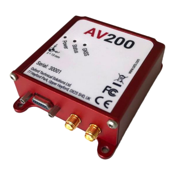
GNSS receivers and inertial sensors is done seamlessly in real-time for a continuous 100 Hz navigation output. Data is automatically logged to the 32 GB eMMC for added data protection. Figure 1 and Figure 2 show the key points of note on the AV200. The numbered labels are described in Table 3. -
Page 10: Dimensions
Measurement origin point LEDs Dimensions Figure 3 shows the outer dimensions of the AV200, the mounting points, and the measurement origin point. When making measurements required in the configuration files, measurements should be made from the origin point. Oxford Technical Solutions Ltd www.oxts.com... -
Page 11: Led Definitions
Figure 3: AV200 dimensions and measurement origin point (mm) LED definitions Table 4, Table 5, and Table 6 show the descriptions for each of the LED functions. Table 4: Power LED Colour Description There is no power to the system or the power supply has failed. -
Page 12: Coordinate Frame
Y-axis points right and the positive Z-axis points down. The AV200 can be mounted in any orientation, it is not necessary for its axes to match those of the host vehicle. The configuration file will specify the transformation from the IMU frame to the vehicle frame. -
Page 13: Figure 4: Av200 Coordinate Frame Axes
Figure 4: AV200 coordinate frame axes Oxford Technical Solutions Ltd www.oxts.com Page 13 of 26... -
Page 14: Design-In
Design-in Main connector The main I/O connector on the AV200 is a 15-way Micro D-sub. Figure 5 shows the pin layout. Figure 5: AV200 main connector pin layout Table 7 shows the pin descriptions. Table 7: Main connector pin description... -
Page 15: User Cable
Figure 6: PPS waveform User cable The AV200 evaluation kit is supplied with a user cable for quick access to the main interfaces. Figure 7 shows the cable diagram and Table 8 shows the pin descriptions for the interface connectors. -
Page 16: Ethernet Configuration
The AV200 outputs its data over Ethernet using a UDP broadcast. The use of a UDP broadcast allows everyone on the network to receive the data sent by the AV200. The data rate of the UDP broadcast is 100 Hz. -
Page 17: Mounting
AV200 by default. Mounting It is essential to mount the AV200 rigidly in the vehicle. The AV200 should not be able to move or rotate compared to the GNSS antennas, otherwise the performance will be reduced. In most circumstances the AV200 should be mounted directly to the chassis of the vehicle. -
Page 18: Antennas
It is important to get the order of the rotations correct. The AV200 can be mounted at any angle in the vehicle as long as the orientation is described in the configuration. This allows the outputs to be rotated based on the settings entered to transform the measurements to the vehicle frame. -
Page 19: Internal Storage
(NAVconfig for configuration files and NAVsolve for data files). The AV200 starts logging data automatically on power-up. Each individual raw data file (*.rd) can be a maximum of 2 GB, equivalent to around one full day of logging at 100 Hz data rate with four GNSS constellations. -
Page 20: Electrical Specifications
Electrical specifications This section lists the recommended electrical operating conditions for the AV200. Table 9: I/O interface electrical specifications I/O signal Input voltage low (V) Input voltage high (V) Output voltage low (V) Output voltage high (V) Output current (mA) Note: triggers are pulled up internally to allow a switch to be used to short them to Ground. -
Page 21: Specifications
Typical values, subject to ionospheric/tropospheric conditions, satellite geometry, baseline length, multipath. Requires clear view of the sky and appropriate differential corrections to achieve full specification. Using dual antenna with 1 m separation baseline. Higher accuracy can be achieved with wider antenna separation. Table 12: AV200 inertial sensor specifications Accelerometers Value Full range ±8 g... -
Page 22: Notes On Specifications
▪ The heading accuracy that can be achieved by the dual antenna system in the AV200 is 0.2° 1σ per metre of separation in ideal, open sky conditions. Increasing the separation improves the performance linearly. -
Page 23: Appendix A - Drawings
Appendix A – Drawings Oxford Technical Solutions Ltd www.oxts.com Page 23 of 26... - Page 24 Oxford Technical Solutions Ltd www.oxts.com Page 24 of 26...
-
Page 25: Revision History
Revision history Table 14: Revision history Revision Comments 210604 Initial draft Oxford Technical Solutions Ltd www.oxts.com Page 25 of 26... - Page 26 Oxford Technical Solutions Park Farm Business Centre Middleton Stoney, OX25 4AL United Kingdom Reg. in England and Wales No. 3534778 © 2021 Oxford Technical Solutions Ltd...
Need help?
Do you have a question about the AV200 and is the answer not in the manual?
Questions and answers