Sign In
Upload
Manuals
Brands
OXTS Manuals
Measuring Instruments
RT3003
OXTS RT3003 Manuals
Manuals and User Guides for OXTS RT3003. We have
2
OXTS RT3003 manuals available for free PDF download: User Manual
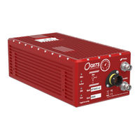
OXTS RT3003 User Manual (133 pages)
Brand:
OXTS
| Category:
Measuring Instruments
| Size: 6 MB
Table of Contents
RT-Range
2
Legal Notices
2
Copyright Notice
2
Revision
2
Contact Details
2
Warranty
3
Table of Contents
4
List of Figures
7
List of Tables
9
Introduction
12
Lane Position Methodology (V2L Feature Code)
12
Figure 1: RT3000 Label Has a Sticker on Top to Show Range Functionality
12
Figure 2: Steps Taken for Lane Position Measurement
13
Distance between Multiple Vehicles Methodology (V2V Feature Code)
14
Distance to Fixed Points and Feature Points Methodology
14
Figure 3: Range Measurements between Two Vehicles
14
Distance to Parking Space
15
Steering Robot Connection
15
RT-Backpack for Pedestrians
15
RT-XLAN y Converter Cables
15
RT-Range S Target
15
Survey Trolley
16
Figure 4: Image of RT-Range S Target with Components
16
Table 1: RT-Range S Target Vehicle Components
16
Table 2: RT-Range Survey Trolley Components
17
Figure 5: Survey Trolley Assembly
18
Figure 6: Survey Trolley
19
Specification
20
Table 3: Technical Specification for Lane Measurements
20
Table 4: Technical Specification for RT3000 V3 with RT-Range Features with RT-XLAN
20
Table 5: Technical Specification for RT3000 V3 with RT-Range Features with Standard Wireless LAN 19 Table 6: Technical Specification for Range Measurements - RT-XLAN
20
Table 7: Technical Specification for Range Measurements - Standard Wireless LAN
21
Installation
22
RT3000 V3 Connections
22
RT-Range Target Connections
22
Hunter Vehicle Wiring
23
Target Vehicle Wiring
23
Figure 7: RT-Range S Front Panel Layout
23
Table 8: RT-Range S Target Front Panel Layout Descriptions
23
Physical Installation
24
Figure 8: Connection Diagram for RT1003 or RT3000 V2 Using RT-XLAN y Converter Cable
24
RT Configuration
25
IP Addresses
25
Figure 9: Ideal Antenna Locations on Top of the Vehicle
25
Survey Trolley Installation
26
Figure 10: Survey Trolley Installation
26
Figure 11: Connection Diagram for the RT on the Survey Trolley
27
Table 9: RT Configuration on the Survey Trolley
27
Physical Orientation
28
Software Configuration
28
Figure 12: Placement of Adapter Plate with RT3000 V3 on a Survey Trolley
28
Table 10: RT Configuration on the Survey Trolley Changes
29
Software
30
Figure 13: Initial Page of RT-Range Software
30
PC Configuration
31
Anti-Virus Software
31
Figure 14: Connection Error Message
31
Feature Point Survey Wizard
32
Figure 15: Windows Firewall Warning Message
32
Creating Feature Points Using Real-Time Measurements
33
Figure 16: Feature Point Survey Wizard Window
33
Deleting Feature Points
34
Editing Feature Points
34
Figure 17: Adjust Trigger Options
34
Figure 18: Feature Point Editor Window
34
Offset Setting
35
Main Controls
35
View Options Control
35
Add Point Control
35
Figure 19: View Options Control in the Feature Point Survey Wizard
35
Figure 20: Add Point Control in the Feature Point Survey Wizard
35
Finish Options Control
36
Display Data Control
36
Figure 21: Finish Options Control in the Feature Point Survey Wizard
36
Figure 22: Display Data Control in the Feature Point Survey Wizard
36
Lane Survey Wizard
37
Overview
37
Selecting a Line Filename
37
Figure 23: Main Screen of the Lane Survey Wizard
37
Connecting to the RT
38
Add Point Option Menu
38
Figure 24: Connection Icon in the RT-Range Line Survey Status Bar
38
Figure 25: IP Addresses RT-Range Navconnect Window
38
Figure 26: Add Point Menu of the Lane Survey Wizard
38
Finish Option Menu
39
Figure 27. Adjust Trigger Options of the Lane Survey Wizard
39
Figure 28: Finish Options of the Lane Survey Wizard
39
Display Data Menu
40
Figure 29: Next Filename Dialog of Lane Survey Wizard
40
Figure 30: Display Data Options of the Lane Survey Wizard
40
Figure 31: Add Windows in the Configure Display Window
41
Figure 32: Add Measurements in the Configure Display Window
41
Table 11: Configure Display Window Descriptions
41
Figure 33: Add Measurements Window
42
Spreadsheet Viewer
43
Map Creation Wizard
43
Selecting a Map Filename
43
Overview
43
Figure 34: Display Item Properties
43
Add Line Options
44
Figure 35: Main Screen of the Map Creation Wizard
44
Figure 36: Add Line Options of the Map Creation Wizard
44
Start Line Option
45
Figure 37: Add Line Options of the Map Creation Wizard
45
Figure 38: Add Multiple Line Files to the Map Creation Wizard
45
Finish Options
46
Figure 39: Setting the Start Line in the Map Creation Wizard
46
Figure 40: Setting the Start Line in the Map Creation Wizard
46
View Options
47
Clean up Line
47
Figure 41: Clean up Line Menu in the Map Creation Wizard
47
Figure 42: Clean up Line Dialog Box in the Map Creation Wizard
47
Map View
48
Figure 43: Clean up Line Example Point
48
Figure 44: Map Point Menu in the Map Creation Wizard
48
Spreadsheet Viewer
49
Figure 45: Map Point Menu in the Map Creation Wizard
49
Table 12: Scale Factors for the Move Function
49
Real-Time Display
50
Overview
50
Configure RT-Range Menu
50
Figure 46: Layout of the Real-Time Display Window
50
RT-Range Quick Config
51
Figure 47: RT-Range Quick Config Introduction Window
51
Figure 48: Longitudinal Offset in the Real-Time Display
52
Figure 49: Using Lateral Offsets Causes Problems on Turns
53
Figure 50: Lateral Offset in the Real-Time Display
53
Figure 51: Fixed Target Setup Window in the Real-Time Display
54
Figure 52: Target Configuration in the Real-Time Display
54
Figure 53: Set Fixed Point Window in the Real-Time Display
55
File Selection Menu
56
Figure 54: RT-Range Quick Config, Local Co-Ordinates Window
56
Display Data Menu
57
Connection Configuration Using the Navconnect Window
57
Figure 55: Connection Icon
57
Figure 56: Select IP Real-Time Addresses; Assign Tag ID and Association Tag
57
Associations and Tags
58
Figure 57: Real-Time Display with Tag ID and Association Tag
58
Bird's Eye View
59
OXTS Data
59
Figure 58: RT-Range Bird's Eye View
59
ISO Data
60
Table 13: Icon Functions in the Bird's Eye View
60
View Configuration
61
Save Data
61
Figure 59: RT-Range Bird's Eye View Configuration
61
Figure 60: RT-Range Data Logger
62
Figure 61: RT-Range Data Logger, File Tab
63
Table 14: Description of the General Tab Parameters
63
Figure 62: RT-Range Data Logger, Start Tab
64
Figure 63: RT-Range Data Logger, Define Start Line
65
Figure 64: Stop Tab
66
RT-Range Configuration Wizard
67
Overview
67
Figure 65: Display Tab
67
Reading the Initial Configuration
68
Hunter / Targets Setup
68
Figure 66: Read Configuration Page of the RT-Range Configuration Wizard
68
Figure 67: RT Addresses RT-Range Configuration Wizard
69
Lane Measurements
70
Figure 68: Typical Positions for Points ABC on a Vehicle
70
Figure 69: Car Lane Measurements in the RT-Range Configuration Wizard
70
Range Measurements
71
Figure 70: Typical Positions for Sensor and Bulls-Eye Points on the Vehicles
71
Defining Polygons
72
Figure 71: Range Measurements, Hunter Tab
72
Figure 72: Configuring Polygon Points
73
Defining Multi-Sensor Points
74
Figure 73: Configuring Polygon Points from an RT
74
Figure 74: Configuring Multi-Sensor Points
75
Options
76
Can
76
Figure 75: Multi-Sensor Point Measurements
76
Figure 76: Options in the RT-Range Configuration Wizard
76
Figure 77: CAN Message Configuration
77
Editing CAN Messages
78
Figure 78: Range, Lane and Hunter Messages
78
Figure 79: Edit Message
78
Figure 80: Configurable CAN Messages for Hunter Navigation Message
79
Local Co-Ordinates
80
Figure 81: Configurable CAN Messages for Hunter Status Messages
80
Range Latency
81
Figure 82: Local Co-Ordinate Setup in the RT-Range Configuration Wizard
81
Range Acceleration Filter
82
Figure 83: ABD Robot Setup Dialog Box
82
Real-Time Polygon-Polygon Calculations
83
Ethernet: Bytes 187 and 188 of the RCOM Extended Range Packet
83
CAN: Rangexpolygon Message, Where X Is the Target Number
83
Advanced
83
Committing the Configuration to the RT3000 V3
84
Figure 84: Range Measurement Plane
84
Saving a Copy of the RT-Range Configuration Locally
85
Figure 85: Commit Page in the RT-Range Configuration Wizard
85
RT-Range Post-Processing Wizard
86
Overview
86
Figure 86: Finish Page in the RT-Range Configuration Wizard
86
Figure 87: Workflow to Convert RD Files to NCOM Files
87
Figure 88: Workflow to Convert NCOM Files to RCOM and CSV Files
87
Select Data Source
88
Read Configuration
88
Figure 89: Hunter NCOM File Selection in the RT-Range Post-Processing Wizard
88
Lane Tracking Mode
89
Figure 90: Read Configuration in RT-Range Post-Processing Wizard
89
Target Setup
90
Figure 91: Lane Position Map File Selection in RT-Range Post-Processing Wizard
90
Figure 92: Target Files Setup Page in the RT-Range Post-Processing Wizard
90
Lane Measurements Setup
91
Range Measurements
91
Options
91
Figure 93: Options Page in the RT-Range Post-Processing Wizard
91
Set Fields
92
Figure 94: Set Fields in the RT-Range Post-Processing Wizard
92
Output Config
93
Figure 95: Output Config Options
93
Output File
94
Figure 96: Output Files Page in the RT-Range Post-Processing Wizard
94
Finish Page
95
Figure 97: Finish Page in the RT-Range Post-Processing Wizard
95
Outputs
96
CAN Bus Messages
96
Heartbeat Messages
97
Signals
98
Table 50: Rangefixedpointhh: Altitude and Heading of Fixed Points, Identifiers 5B2H (1458), 5C2H (1474), 5D2H (1490), 5E2H (1506)
107
Table 51: Rangesensorleverarm: Lever Arm from the RT to the Sensor Point, Identifiers 5B3H (1459), 5C3H (1475), 5D3H (1491), 5E3H (1507)
107
Table 52: Rangebullseyeleverarm: Lever Arm from the RT to the Bulls-Eye Point, Identifiers 5B4H (1460), 5C4H (1476), 5D4H (1492), 5E4H (1508)
107
Table 53: Rangevehicle: User Parameters about the Target Vehicle, Identifiers 5B5H (1461), 5C5H (1477), 5D5H (1493), 5E5H (1509)
107
Table 54: Rangeposstdev: Standard Deviation of the Range Measurements, Identifiers 5B6H (1462), 5C6H (1478), 5D6H (1494), 5E6H (1510)
108
Table 55: Rangefeatpointll: Latitude and Longitude of Feature Points, Identifiers 5B7H (1463), 5C7H (1479), 5D7H (1495), 5E7H (1511)
108
Table 56: Rangefeatpointhh: Altitude and Heading of Feature Points, Identifiers 5B8H (1464), 5C8H (1480), 5D8H (1496), 5E8H (1512)
108
Calculation Details
109
Range Measurement Effects
109
2D and 3D Measurement Planes
109
Figure 98: Horizontal (2D) Measurement Plane Calculation
109
Polygons
110
Figure 99: Hunter (3D) Measurement Plane Calculation
110
Range Velocity with Polygons
111
Errors in Heading
111
Figure 100: Polygon Point or Edge Tracking
111
Lateral Velocity Effects
112
Transient Errors Due to Communication Link Delay
112
Figure 101: Lateral Velocity of the Target Compared to the Hunter
112
Table 57: Lateral Error for Different Ranges for 0.1 Deg Heading Error
112
Lane Position Measurement Effects
113
Figure 102: Example Transient Error for 0.8 G Acceleration on Target Vehicle
113
Figure 103: Fitting between the Points on the Lines
114
Discontinuous Distance
115
Figure 104: Discontinuous Distance at the Points
115
Co-Ordinates for Measurements with Respect to the Lines
116
Acceleration on Curves
116
Effect of the Line Survey on the Accuracy
116
Figure 105: Co-Ordinate System for the Line Measurements
116
Figure 106: Error Using Straight Lines to Approximate Curves
117
Table 58: Curve Fitting Error for 1 M Point Separation
117
Rules for the Clean up Line Tool in the Map Creation Wizard
118
Line, Map and Feature Point File Format Descriptions
119
Line File Format
119
Map File Format
119
Table 59: Line File Format
119
Header Fields
120
Figure 107: Example Map File
120
Line Fields
121
Feature Point File Format
121
Table 61: Line Format in the Map File
121
Table 62: Feature Point File Header Fields
122
Figure 108: Example Feature Point File
123
Table 63: Feature Point File Fields
123
RT-Range and the Ibeo Feature Fusion ADAS Reference System
124
Introduction to the Ibeo Feature Fusion System
124
Benefits of Adding the Ibeo Feature Fusion System to the RT-Range System
124
Ibeo Laser View (ILV) Visualisation
125
Figure 109: Ibeo Laser View (ILV) Data Visualisation
125
Revision History
127
Blank for User Notes
129
Table 64: Revision History
129
Advertisement
OXTS RT3003 User Manual (132 pages)
GNSS-aided inertial measurement systems
Brand:
OXTS
| Category:
Measuring Instruments
| Size: 3 MB
Table of Contents
Table of Contents
6
Introduction
10
Easy Operation
11
Self-Correcting
11
Interchangeable
11
Advanced Processing
11
Related Documents
12
RT Product Family
13
Single Antenna
13
Dual Antenna
13
Glonass
14
250 Hz
14
Satellite Differential Corrections
14
Scope of Delivery
16
RT2000 System Components
16
RT3000 System Components
17
RT4000 System Components
18
Specification
20
Common Specifications
24
Notes on Specifications
24
Heading Accuracy
25
Environmental Protection
25
GNSS Antenna Operating Temperature
25
Safety Information
25
Export Control Classification Number
25
Conformance Notices
27
Regulator Testing Standards
27
Software Installation
29
Hardware Installation
31
RT Orientation and Alignment
31
Antenna Placement and Orientation
31
Operation
33
Front Panel Layout
33
LED Definitions
35
Co-Ordinate Frame Conventions
37
IMU Frame
37
Oxts NED Navigation Frame
39
ISO 8855 ENU Earth-Fixed System
39
Oxts Horizontal Frame
40
ISO 8855 Intermediate System
41
Oxts Vehicle Frame
42
ISO 8855 Vehicle System
43
Ethernet Configuration
43
Connection Details
45
Dual Antenna Systems
46
Multipath Effects on Dual Antenna Systems
48
Inputs and Outputs
49
Digital Inputs and Outputs
49
1PPS Output
50
Event Input
50
Wheel Speed Input
51
Wheel Speed Output
51
IMU Sync Output Pulse
51
Reverse Polarity Protection
51
Configuring the RT
53
Overview
53
Selecting the Operating Language
54
Navigating through Navconfig
54
Product Selection
54
Reading Configuration
55
GNSS Selection
57
Orientation
57
Get Improved Settings
59
Primary Antenna
61
Secondary Antenna
63
Advanced Slip
64
Options
66
Vehicle Starts
67
Vibration
67
GNSS Environment
68
Differential Correction
68
Sbas
70
DGNSS Service
70
Can
71
Heading Lock
77
Garage Mode
78
Initialisation Speed
78
Displace Output
78
Distance Output
79
Analogue Output
79
Acceleration Filter
80
Wheel Speed Input
81
Local Co-Ordinates
83
Serial 1 Output
84
Ethernet Output
86
Steering Robot IP
88
Output Smoothing
88
Slip Points
89
GNSS Control
90
Surface Tilt
92
Coordinate System
93
Advanced
94
Committing the Configuration to the RT
95
Saving the Configuration and Finishing
96
Setting up the Base Station
97
Using the RT-Base S
97
Initialisation Process
98
Real-Time Outputs
98
Warm-Up Period
99
Post-Processing Data
103
Laboratory Testing
104
Accelerometer Test Procedure
104
Gyro Test Procedure
104
Testing the Internal GNSS and Other Circuitry
106
Using the Orientation Measurements
107
Operating Principles
108
Internal Components
108
Strapdown Navigator
109
Kalman Filter
110
CAN Messages and Signals
112
Termination Resistor
112
CAN-DB File
112
CAN Bus Messages
112
Signals
115
Revision History
131
Drawing List
132
Advertisement
Related Products
OXTS RT3000
OXTS RT3000s
OXTS RT3100
OXTS RT3102
OXTS RT3100G
OXTS RT3102G
OXTS RT3002
OXTS RT3002G
OXTS RT3003G
OXTS RT2500-250
OXTS Categories
Measuring Instruments
Car Navigation system
GPS
UPS
Test Equipment
More OXTS Manuals
Login
Sign In
OR
Sign in with Facebook
Sign in with Google
Upload manual
Upload from disk
Upload from URL