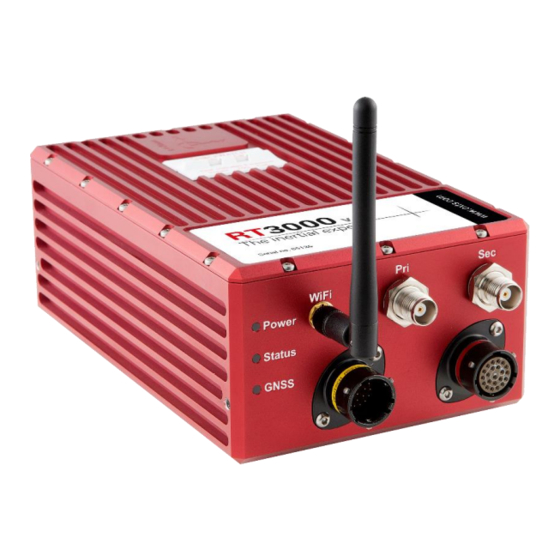
OXTS RT3000 User Manual
Gnss-aided inertial measurement systems
Hide thumbs
Also See for RT3000:
- User manual (105 pages) ,
- Quick start manual (12 pages) ,
- User manual (133 pages)


Need help?
Do you have a question about the RT3000 and is the answer not in the manual?
Questions and answers