Advertisement
Quick Links
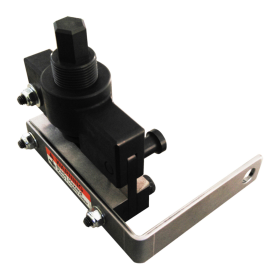
Operator's Manual for
ProCut Belt Cutter (720905-1)
Manufactured by: Safeworks | 365 Upland Drive, Seattle, WA 98188
Phone: (855) 457-8513 | Fax: (206) 575-6240
Email: ProductSupport@SpiderStaging.com | Website: SpiderStaging.com
Document No: 720900-1
Issue Date: 2018-Sep-20
Revision: C
Page 1 of 13
This document and all copies are the property of Safeworks. All dimensions and data are indicative only.
The user must ensure that the equipment complies with local rules and regulations.
Advertisement

Summary of Contents for Brand Safway Spider ProCut
- Page 1 Operator’s Manual for ProCut Belt Cutter (720905-1) Manufactured by: Safeworks | 365 Upland Drive, Seattle, WA 98188 Phone: (855) 457-8513 | Fax: (206) 575-6240 Email: ProductSupport@SpiderStaging.com | Website: SpiderStaging.com Document No: 720900-1 Issue Date: 2018-Sep-20 Revision: C Page 1 of 13 This document and all copies are the property of Safeworks.
- Page 2 WARNING • All persons operating this belt cutter must read and completely understand this manual. • Only authorized persons shall operate this belt cutter. • Only use an impact wrench with max. torque of 350 Nm (260 ft lb) • Any operation in violation of these instructions is at the operator’s own risk and may result in serious injuries.
- Page 3 1. PARTS OF THE PROCUT BELT CUTTER Top Block Threaded Rod UP-12636.04 UP-12636.06 Detent Pin Shoulder Screw M8x25 UP-12636.08 722272-1 Washer 8 mm 8864 Lock Nut M8 8883 Blade UP-12636.05 Spring Plunger 2x UP-12487 Screw M10x60 2x 722271-1 Shear Ram Washer 10 mm Holder 1 4x 8865...
- Page 4 2. HOW TO USE THE PROCUT BELT CUTTER Step 1: Turn the threaded rod counterclockwise until it is fully seated against the top block. Top Block Step 2: Pull out the detent pin and open the belt cutter. NOTE: The detent pin will stop after the first catch. Do not force the pin further.
- Page 5 Step 3: Place belt cutter jaws around elevator belt. NOTE: Ensure belt lays flat between the between the top block and shear ram holders. Elevator Belt Step 4: Close the jaws around the belt and push the detent pin back in as shown below.
- Page 6 Step 5: Using a 19 mm (or 3/4”) socket and impact wrench on the hex end of the threaded rod, drive the belt cutter blade through the elevator belt. Step 6: Remove cut section of belt and reverse the impact wrench to return the blade to the neutral position.
- Page 7 3. SERVICING THE PROCUT BELT CUTTER Disassembly Step 1: Pull out the detent pin as far as it will go and open the belt cutter. Step 2: Screw threaded rod clockwise to lower the blade. Slide the blade sideways off the round end of the threaded rod. Step 3: ...
- Page 8 Step 4: If replacing shear rams, shear ram holders, or handle, remove the two M10x60 bolts using two 16 mm wrenches. Servicing Step 1: Every 100 cuts or when all wires are no longer cutting cleanly, inspect the threaded rod and top block for thread damage and replace as necessary.
- Page 9 Step 2: Apply Wurth CU 800 Copper Anti-Seize to the threads of the threaded rod and to the inside of threaded hole in the Top Block. Apply copper anti-seize to rod and Top Block threads Reassembly Step 1: Orient Shear Ram 1 so that the cutout in the bolt hole reinforcement faces DOWN.
- Page 10 Step 2: Orient Shear Ram 2 so that the cutout in the bolt hole reinforcement faces DOWN. Align the holes of Shear Ram 2 with the holes on Shear Ram 1 and the Handle as shown below. Insert the two long bolts with a washer through Shear Ram 2, each Shear Ram Holder, Shear Ram 1, and the Handle.
- Page 11 Step 3: Insert the Detent Pin into the Top Block as shown below. Screw the first two threads of the two Spring Plungers into the bottom of the Top lock using small flathead screwdriver. Apply Loctite 243 to the remaining threads of the spring plungers and continue to screw them in.
- Page 12 Step 5: Screw the Threaded Rod into the Top Block just far enough to slide the blade sideways onto the round end of the threaded rod. Once the blade is in place and aligned with the channel of the Top Block, continue to screw the Threaded Rod to draw the blade up into the top block.
- Page 13 Step 7: Pull out the detent pin and slide the top block onto shear ram holder 1. Align the holes and push in the detent pin. Document No: 720900-1 Issue Date: 2018-Sep-20 Revision: C Page 13 of 13 This document and all copies are the property of Safeworks. All dimensions and data are indicative only. The user must ensure that the equipment complies with local rules and regulations.
Need help?
Do you have a question about the Spider ProCut and is the answer not in the manual?
Questions and answers