
Related Manuals for Carver Yachts 38 Super Sport


Summary of Contents for Carver Yachts 38 Super Sport
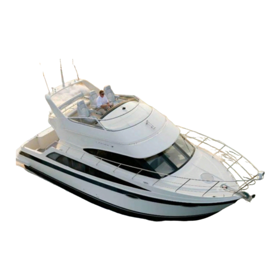
- Page 1 38 Super Sport Owner’s Guide HIN: CVRU2099D010 2010 Version 1 https://www.boat-manuals.com/...
- Page 2 https://www.boat-manuals.com/...
- Page 3 Marquis Yachts, L.L.C. 790 Markham Drive P.O. Box 1010 Pulaski, WI 54162-1010 Phone (920) 822-3214 Fax (920) 822-3213 www.carveryachts.com Robert VanGrunsven President Congratulations and Welcome Aboard! This Owner’s Guide was designed to acquaint you with the safe, proper operation and maintenance of your new boat and its systems.
- Page 4 https://www.boat-manuals.com/...
-
Page 5: Table Of Contents
able of onTenTs Preface Section 3 - AC Electrical System Using Your Owner’s Information Kit ..i System Organization ....1 Owner’s Guide . - Page 6 https://www.boat-manuals.com/...
- Page 7 able of onTenTs Section 6 - Operating and Section 8 - Winterization Maneuvering and Storage Launching the Boat ....1 Winterization - Storage ....1 Navigation .
- Page 8 https://www.boat-manuals.com/...
-
Page 9: Using Your Owner's Information Kit
refaCe Using Your Owner’s Information Kit Your Owner’s Information kit contains this Owner’s Guide and a set of manuals referred to as “OEM information.” Please read the Owner’s Guide and OEM information carefully and familiarize yourself with your boat before operating the boat or any of its components or systems. IMPORTANT: The Owner’s Information kit must be onboard whenever your boat is operated. -
Page 10: Oem Information
refaCe OEM Information The OEM (Original Equipment Manufacturer) information is supplied by companies from whom Carver has purchased components to install in your boat. These components include, but are not limited to, standard items like the engines, sanitation system, various pumps, and 12-volt batteries, as well as optional items. - Page 11 THIRD OWNER REGISTRATION Owner's Name: ______________________________________________ Street Address: ______________________________________________ City: _____________________ State: _______ Zip Code: ____________ Telephone: ( ___) __________________Date of Purchase: ___________ Purchased From: _____________________________________________ Boat Hull Identification Number: CDR ___________________________ Third Owner Registration does not extend, alter, or transfer the Carver Limited Warranty.
- Page 12 MARQUIS YACHTS, L.L.C. PO BOX 1010 PULASKI WI 54162-1010 MARQUIS YACHTS, L.L.C PO BOX 1010 PULASKI WI 54162-1010 https://www.boat-manuals.com/...
-
Page 13: Section 1 - Boating Safety
oating afety ection Boating Safety Boating safety is your responsibility. You must fully understand the operating procedures and safety precautions in the Owner’s Information kit and this owner’s guide before you operate your new boat. Safe boating is no accident. Safe Operation Safe operation includes, but is not limited to, the following. - Page 14 oating afety ection Adverse Conditions Weather At all times, the boat operator should be aware of present weather conditions and the weather forecast. Check the forecast before you begin a day of boating. Be aware, however, that weather conditions can change rapidly.
-
Page 15: Emergency Procedures
oating afety ection Fog is a result of either warm-surface or cold-surface conditions. You can judge the likelihood of fog formation by periodically measuring the air temperature and dew point temperature. If the difference between these two temperatures is small, fog is likely to develop. Remember the following guidelines: •... - Page 16 oating afety ection Never: • Obstruct passage ways to exits and hatches. • Obstruct safety controls, such as fuel valves and electrical system switches. • Obstruct portable fire extinguishers in lockers. • Leave the boat unattended when cooking or heating appliances are in use.
- Page 17 oating afety ection Swamped or Capsized Boat If your boat becomes swamped or capsizes, put on a personal flotation device immediately and set off a distress signal. Chances are good a capsized boat will stay afloat. For this reason, stay with the boat. Do not leave the boat or try to swim to shore except under extreme conditions.
- Page 18 oating afety ection Man Overboard You should know what to do in case someone falls overboard. Emergency procedures are published in Chapman’s and instruction is offered by the U.S. Coast Guard. If a person falls overboard, hypothermia may be an immediate concern. Hypothermia occurs when a person’s body loses heat faster than the body can replace it.
-
Page 19: Safety Equipment
oating afety ection Safety Equipment (this next section to page 11 applies for U.S. ownership only) Note: Federal law requires you to provide and maintain safety equipment onboard your boat. Consult U.S. Coast Guard, state and local regulations to ensure your boat has all required safety equipment onboard. - Page 20 oating afety ection Approved non-pyrotechnic equipment includes: • Orange distress flag • Dye markers • Electric distress light. No one signaling device is ideal under all conditions. Consider carrying of visual distress equipment are very important. Select devices with packaging that children, but not adults, will find difficult to open, especially if young children are onboard.
-
Page 21: Owner's Responsibilities
oating afety ection Recommended Equipment In addition to required equipment, you may want to carry the following: • Spare anchor • Heaving line • Fenders • Flashlight • Mirror • Suntan lotion • Spare propeller(s) • Tool kit • Ring buoy •... - Page 22 oating afety ection Other helpful publications available from the U.S. Coast Guard include Aids to Navigation (U.S. Coast Guard pamphlet #123), which explains the significance of various lights and buoys; the Boating Safety Training Manual and Federal Requirements For Recreational Boats. Check with your local U.S.
- Page 23 oating afety ection Boating Accidents The operator of a vessel used for recreational purposes is required to file a report whenever an accident results in loss of life or disappearance from a vessel, an injury requiring medical treatment beyond first aid, property damage in excess of $200 or complete loss of the vessel.
-
Page 24: Carbon Monoxide (Co) Warnings
oating afety ection Pre-Departure Actions • Check the weather. Make sure conditions and seas will not be hazardous during your voyage. • Make sure all safety equipment is onboard, accessible and in good working condition. • Check the bilge for fuel vapor or water. Ventilate or pump out the bilge as necessary. - Page 25 oating afety ection People sleeping onboard can easily be overcome by carbon monoxide without realizing it. Do not sleep while the engines or generators are running. • Keep the engine room hatch closed when operating the engines and generator. • Do not occupy aft lounging areas, including the boarding platform, or swim near the engine or generator exhaust outlets while the engines or generator are running.
- Page 26 oating afety ection The following chart displays some possible situations where CO may accumulate. Become familiar with these examples and the suggested precautions to help prevent a dangerous accident. Blockage of exhaust outlets PRECAUTION: Never operate can cause carbon monoxide the generator while the boat to accumulate in the cabin and is moored against any other...
-
Page 27: Identifying Co Exposure
oating afety ection Identifying CO Exposure In high concentrations, CO can be fatal in minutes; however, the effects of lower concentrations can also be lethal. Symptoms of exposure to CO are: • Watering and itchy eyes • Flushed appearance • Throbbing temples •... - Page 28 oating afety ection This page intentionally left blank. 3827 • U2 3/10 https://www.boat-manuals.com/...
-
Page 29: Dc Electrical System
DC E lECtriCal yStEm ECtion DC Electrical System Your boat is equipped with a 12-volt DC (Direct Current) electrical system. This is a comprehensive system that is designed to meet your present and future 12-volt electrical needs. Wire-runs and connections are positioned to prevent abrasion and exposure to moisture, as well as to remain accessible for inspection, repairs, and the addition of aftermarket electrical accessories. - Page 30 DC E lECtriCal yStEm ECtion Batteries- Engine Room Forward Accessory Main Starboard Engine Port Engine Batteries and Disconnect Switch- Generator Aft Refer to page 5 section 3 for location of Generator Generator Battery Generator Disconnect Accessory Battery Electricity from the battery to the Safety Breaker Panel is controlled by a master disconnect switch.
- Page 31 DC E lECtriCal yStEm ECtion Safety Breaker Panel and Battery Chargers - Engine Room DC Control Panel - Salon DC Volt Meter Generator Stop/Start Monitoring Battery voltage Levels A fully charged battery that has not been charged or discharged for at least two hours should indicate between 12.3 and 12.6 volts;...
-
Page 32: Battery Maintenance
DC E lECtriCal yStEm ECtion Accessory Batteries You can determine the voltage level of the Accessory Batteries using the voltmeter located on the DC Control Center. To activate the voltmeter: 1. Turn the Accessory Battery master disconnect switch to the ON position. 2. -
Page 33: Operating The 12-Volt Equipment
DC E lECtriCal yStEm ECtion • Keep the batteries fully charged. Batteries that are kept fully or near fully charged last longer than batteries stored with a partial charge. The charge level of the batteries can be monitored using the voltmeters on the helm instrument panel. -
Page 34: Dc Control Center
DC E lECtriCal yStEm ECtion Never reset a breaker that has been automatically tripped without first correcting the problem. Failure to follow this procedure may create a dangerous situation. NOTE: Sometimes a circuit breaker location is labeled but no circuit breaker is present. -
Page 35: Bridge Breaker Panel
DC E lECtriCal yStEm ECtion Spare(s) These breakers are reserved for aftermarket accessories you install on your boat. Spotlight This breaker controls the control panel for the spotlight. The controls are located at the helm. Refer to the OEM information for details on operating the spotlight. -
Page 36: Safety Breaker Panel
DC E lECtriCal yStEm ECtion Bridge Breaker Panel The Bridge Breaker Panel, located below the port side of the bridge helm, protects the circuitry between the DC Control Center and the optional electronics package installed at the helm. The circuit breakers on this panel are normally ON and cannot be manually switched OFF. - Page 37 DC E lECtriCal yStEm ECtion Auto Bilge Pump - Forward, Mid, and Aft These breakers control the bilge pumps. Each pump is activated automatically by a float switch whenever water within the bilge rises to a predetermined level. Make sure these breakers are ON whenever the boat is in the water.
- Page 38 DC E lECtriCal yStEm ECtion Main - One This breaker protects the circuitry between the DC Control Center and the Accessory Battery. This breaker must be ON to provide power to the DC Control Center. Main - Two This breaker helps protect the circuitry between the Bridge Breaker Panel and the Accessory Battery.
- Page 39 DC E lECtriCal yStEm ECtion Problem Possible Cause Possible Solution Accessory Battery master Turn the switch to the 12-volt equipment does disconnect switch is in the OFF ON position. not function. position. Main-One or Main-Two circuit Turn both circuit breakers ON. breaker on the Safety Breaker Panel is OFF.
- Page 40 DC E lECtriCal yStEm ECtion SALON DC GRD BRIDGE GRD 8 STUD 8 STUD 8 STUD 8 STUD 8 STUD 8 STUD 3827 • U2 3/10 https://www.boat-manuals.com/...
-
Page 41: Ac Electrical System
AC E lECtriCAl yStEm ECtion AC Electrical System Your boat is equipped with a 50 amp AC (alternating current) electrical system. The power for this system is supplied by either a shore power source or the generator. The procedures for connecting to a shore power source and to the generator are explained later in this section. - Page 42 AC E lECtriCAl yStEm ECtion Do not supply power to a boat that has not had its water system fully charged. Doing so will damage the unit’s water heater. 1. Make sure the generator is not running. 2. On the AC Control Center, located in a cabinet in the aft starboard side of the salon, switch the Water Heater circuit breaker OFF.
- Page 43 AC E lECtriCAl yStEm ECtion Shore Power Breakers- Aft locker Shore Power - Aft Connections Shore Tv Connection Make sure the shore power cord(s) you use is in excellent condition with no cuts, nicks or abrasions in the exterior plastic cover. Also make sure that the cord(s) is specifically designed to connect your boat to a shore power source. Using a damaged cord or a cord that is not designed for this purpose can cause electrical shock resulting in death or serious injury.
-
Page 44: Generator Power
AC E lECtriCAl yStEm ECtion 12. Switch the circuit breaker that is installed in the shore power source box ON. 13. Switch the AC Main circuit breaker group(s) ON. 14. There is a Reverse Polarity indicator on the AC Control Center for Shore #1 and Shore #2. - Page 45 AC E lECtriCAl yStEm ECtion GENERATOR OPTIONS Master Switch Strainers and Seacocks Cooling Water Intake System Exhaust System Port Fuel Tank Generator Fuel Soleniod Water Pickup Strainer Exhaust Outlet Mu er Muffler Battery 2. The generator starter is powered by its own 12-volt battery. Turn the generator battery master disconnect switch to the ON position.
- Page 46 AC E lECtriCAl yStEm ECtion Never turn the generator battery master disconnect switch to the OFF position while the generator is operating. Doing this can damage the generator or its alternator wiring. 3. The generator engine uses a seawater cooling system. This system includes a strainer that prevents debris in the seawater from entering the cooling system’s water pump.
-
Page 47: Operating Ac Equipment
AC E lECtriCAl yStEm ECtion 10. Push the spring-loaded generator STOP/START switch, located on the DC Control Center, to the START position and hold it there until the generator starts. Release the switch when the generator starts. If the generator does not start within 10 seconds, release the STOP/ START switch, wait 1 minute, then try to start the generator again. -
Page 48: Ac Control Center
AC E lECtriCAl yStEm ECtion AC Control Center The AC Control Center, located in the cabinet in the starboard side of the salon, manages the power supply to all of the boat’s AC equipment. To provide power to this breaker panel, first provide a source of AC power to the boat, either through a shore power connection or the generator, as described earlier in this section. - Page 49 AC E lECtriCAl yStEm ECtion Ammeter The ammeter indicates the amount of current that is being drawn by the selected line circuit. When the appropriate Shore (1 or 2) or Generator circuit breaker group is ON, all other breakers on the AC Control Center are OFF, and the voltmeter is reading between 100 and 130 volts in a 120-volt system (210 and 230 volts in a 220-volt system), the ammeter should read zero amps.
- Page 50 AC E lECtriCAl yStEm ECtion Reverse Polarity Indicators These indicators illuminate when the polarity of the shore power source for the respective line circuit is incorrect. Refer to Section 3 - Shore Power for information on correcting reverse polarity. If reverse polarity occurs, immediately switch the respective Shore circuit breaker group OFF.
-
Page 51: Ground Fault Circuit Interrupters
AC E lECtriCAl yStEm ECtion If you are using shore power, make sure: • Your shore power cord is properly attached to both the boat and the shore power source. • The appropriate circuit breaker at the shore power source box is ON. •... -
Page 52: Testing Gfci Receptacles
AC E lECtriCAl yStEm ECtion Testing GFCI Receptacles The GFCI receptacles are identified by Test and Reset buttons located between the receptacles’ two outlets. Test each GFCI receptacle once every week: 1. Press the Test button. If the GFCI is operating normally, this cuts the power supply to the GFCI receptacle and to all other receptacles on that circuit. -
Page 53: Electrical Loads
AC E lECtriCAl yStEm ECtion ELECTRICAL LOADS AC Device Approximate Maximum Current Used (Amps) Refrigerator Electric blanket Television Coffee maker Battery charger Toaster 10.5 Frying pan 12.3 Bonding System Your boat is equipped with a comprehensive metallic bonding system that interconnects all underwater equipment and thru-hull fittings. The bonding system ensures that the “cases”... -
Page 54: Troubleshooting The Dc Electrical System
AC E lECtriCAl yStEm ECtion Troubleshooting the AC Electrical System Problem Possible Cause Possible Solution Shore power cord is not Connect the shore voltmeter on the AC Control connected. power cord. Center reads zero volts. There is no power at the Contact marina shore power source box. - Page 55 AC E lECtriCAl yStEm ECtion AC Wiring Schematics 3827 • U2 3/10 https://www.boat-manuals.com/...
- Page 56 AC E lECtriCAl yStEm ECtion This page intentionally left blank. 3827 • U2 3/10 https://www.boat-manuals.com/...
-
Page 57: Air Conditioning System
nternal yStemS ectIon Air Conditioning System Air Conditioning System For the air conditioning system to operate, it needs a source of AC power For the air conditioning system to operate, it needs a source of AC power (supplied by either a shore power source or the generator) and a supply of (supplied by either a shore power source or the generator) and a supply of seawater (either salt or fresh). - Page 58 nternal yStemS ectIon Air Conditioning System Pump Strainer 3827 • U2 3/10 https://www.boat-manuals.com/...
- Page 59 nternal yStemS ectIon 8. Use the controls for each air conditioning unit to set the desired temperature. The controls are located in the salon and master stateroom. Refer to the OEM information for details on operating the air conditioning controls. Fresh Water System The capacity of your boat’s fresh water system is approximately 86 gallons.
-
Page 60: Fresh Water System
nternal yStemS ectIon FRESH WATER SYSTEM Aft Shower Water Pump Shore Water 3827 • U2 3/10 https://www.boat-manuals.com/... - Page 61 nternal yStemS ectIon 8. Use the controls for each air conditioning unit to set the desired temperature. The controls are located in the salon and master stateroom. Refer to the OEM information for details on operating the air conditioning controls. Fresh Water System The capacity of your boat’s fresh water system is approximately 86 gallons.
- Page 62 nternal yStemS ectIon the hot water faucet for that tap or shower head. When you have done this for each sink tap and shower head, the water system is primed. 6. Add water to the fresh water tank to replace that which was used in the previous step.
- Page 63 nternal yStemS ectIon NOTE: The sump pump can not operate if the Auto Sump circuit breaker is OFF. Make sure the circuit breaker is ON before using the showers or sinks. Cockpit Hand Shower The cockpit hand shower enables you and your guests to rinse off with warm, fresh water after swimming without having to enter the cabin.
- Page 64 nternal yStemS ectIon To connect to shore water: 1. Locate the shore water fitting, labeled SHORE WATER. Refer to the Fresh Water System diagram in this section for the exact location of this fitting. (page 4) 2. Attach one end of a garden hose to the shore water fitting. 3.
-
Page 65: Bilge System
nternal yStemS ectIon BILGE SYSTEM Forward Bilge Pump Forward Bilge Pump Discharge Amidships Bilge Amidships Bilge Pump Pump Discharge Aft Bilge Pump Discharge Aft Bilge Pump 3827 • U2 3/10 https://www.boat-manuals.com/... - Page 66 nternal yStemS ectIon A Tip From Carver! A small amount of water always collects in your boat’s bilge. This water is usually not enough to activate an automatic float switch. While underway and on plane, use the helm switches to manually turn the bilge pumps on and let them run for 30 seconds to a minute. When your boat is on plane, water in the bilge flows to the stern, where the aft bilge pump is located.
- Page 67 nternal yStemS ectIon A Tip From Carver! Coat the threads of the hull drain plug with waterproof grease before you install the plug into the hull drain fitting. This makes it easier to remove the plug at a later date. Sanitation System Your boat’s sanitation system includes the head, waste tank and optional overboard waste discharge system.
-
Page 68: Sanitation System
nternal yStemS ectIon SANITATION SYSTEM vacuum Pump Selector valve Waste Tank Discharge Pump Discharge Pump Switch Waste Cap 3827 • U2 3/10 https://www.boat-manuals.com/... - Page 69 nternal yStemS ectIon 3. Attach the pumpout vacuum hose to the WASTE deck fitting. Because the transfer process uses a vacuum action, there must be a secure connection between the transfer hose and the deck fitting. 4. Activate the pumpout vacuum. The pumpout vacuum transfers onboard waste to the dockside holding station.
- Page 70 nternal yStemS ectIon This page intentionally left blank. 3827 • U2 3/10 https://www.boat-manuals.com/...
-
Page 71: Section 5 - Propulsion
roPulsion ection Propulsion This section gives a general overview of your propulsion system and how it works. For a detailed explanation of the engines installed in your boat, refer to the OEM information. Fuel Systems Gasoline Fuel Systems Each gasoline propulsion engine in your boat is plumbed to the fuel tank located on the same side of the boat as the engine. - Page 72 roPulsion ection FUEL SYSTEM Fuel Filters To Deck Plate To Deck Plate Fuel Filters Mufflers 3827 • U2 3/10 https://www.boat-manuals.com/...
-
Page 73: Fire Suppression System
roPulsion ection Fuel Shut-Off valves Gasoline engines models do not have manual fuel shut-off valves. This system utilizes anti-siphon check valves. These engines also do not have return lines or fuel crossovers. Fire Suppression System An automatic fire suppression system is installed in the engine room. This system provides extra security in the event of an engine room fire. -
Page 74: Engine Room Ventilation
roPulsion ection Engine Room ventilation Your boat’s engine room is equipped with a ventilation system consisting of intake ducts, exhaust ducts and bilge blowers. This system is designed to remove any fuel vapor from the engine room. The bilge blowers operate whenever the engines are running, as long as the four Bilge Blower circuit breakers on the DC Control Center are ON. -
Page 75: Exhaust System
roPulsion ection can flood the non-running engine with seawater, damaging it. Before you restart the non-running engine, open its seacock again. Running an engine with an inadequate supply of antifreeze, or with obstructed or restricted seawater pickups or strainers can cause serious damage to the engine and its related systems. If the engine temperature gauges show a higher than normal temperature, the respective cooling system may need to be repaired. If the gauge needle moves quickly toward a high temperature, immediately shut off the affected engine and have the cooling system inspected and repaired. - Page 76 roPulsion ection Temperature Gauge The temperature gauge displays the temperature of the coolant in the engine’s cooling system. Every engine is designed to operate within a specific temperature range. Refer to the engine OEM information for the normal operating temperature range of your engines. A sudden increase in the temperature gauge reading could indicate that the cooling system has become blocked;...
-
Page 77: Helm Controls
roPulsion ection Gauge Maintenance The gauges on the helm instrument panel should be protected from the sun and weather when not in use. The gauges are not waterproof. Protecting them from the elements prolongs their life. NOTE: Small beads of moisture (condensation) can form behind the glass bezel on some gauges. This does not mean the gauge is defective. The Carver Limited Warranty does not cover the replacement of gauges that are cosmetically affected by condensation. -
Page 78: Preparing For Cruising
roPulsion ection For the optional electronic controls, the shift/throttle levers from the helm are connected to the engines by an electronic control system. Refer to the OEM information for details on adjusting and maintaining the shift/throttle control systems. Steering Your boat uses a hydraulic steering system. This system is preferable over a mechanical steering system because it provides better response for large boats. - Page 79 roPulsion ection You must use the correct fuel for your boat’s engines. Refer to the engine OEM information for the recommended type of fuel. Avoid spilling fuel on the gelcoat surface of your boat. Fuel can stain the gelcoat and damage any hull accent stripes that may have been applied 10. Your boat’s fuel tanks are designed to take on fuel at a maximum rate of 9 gallons per minute (GPM) when the tank is between 25% and 75% full.
- Page 80 roPulsion ection b. Verify that all of the safety circuit breakers are ON. c. If needed, switch ON the Windlass, Manual Sump and Electric Head circuit breakers. 6. On the DC Control Center: a. Switch the System DC Main circuit breaker ON. b.
- Page 81 roPulsion ection If the engine is cold when it starts, it may run rough. Advance its shift/ throttle lever slightly to keep it running. 5. When the engine is idling smoothly, start the other engine in the same manner as the first. After the Engines Have Started Check the engine gauges.
- Page 82 roPulsion ection This page intentionally left blank 3827 • U2 3/10 https://www.boat-manuals.com/...
-
Page 83: Launching The Boat
perating and aneuvering ectiOn Launching the Boat Have a professional launch your boat. Your dealer can either provide experienced people to do this or recommend someone. Navigation Understanding navigation is very important when operating your boat on the open seas. Instructions on how to navigate your boat are beyond the scope of this guide. -
Page 84: Controlling The Boat
perating and aneuvering ectiOn Controlling the Boat Every boat owner should know how to perform the following procedures competently. Do not attempt any of these procedures without first receiving appropriate training. Loading When you load items onto the boat, have someone on the pier hand them to you after you have boarded the boat. - Page 85 perating and aneuvering ectiOn Picking Up a Mooring As you return to the anchorage, approach your mooring at slow speed. Take note of how other boats are lying at their buoys. They are heading into the wind or current and your approach course should be roughly parallel to their heading.
- Page 86 perating and aneuvering ectiOn Check sternway (stop reverse motion) by shifting your engines to forward gear and throttling forward. Full stern turns can be executed, but watch the bow. The bow cuts a much wider arc than the stern and collisions could occur in crowded areas. Checking Headway Stopping the boat’s forward motion is referred to as “checking headway.”...
- Page 87 perating and aneuvering ectiOn Tracking Forward (Props Only) Starboard Engine Forward Both Engines Forward Port Engine Forward Tracking Astern (Props Only) Starboard Engine Reverse Port Engine Reverse Both Engines Reverse 3827 • U2 3/10 https://www.boat-manuals.com/...
-
Page 88: Anchoring
perating and aneuvering ectiOn Towing Always offer assistance to a vessel in distress. However, towing a capsized boat or a boat with a damaged hull is not recommended. In these situations, lend aid to the occupants and call the proper authorities. Remember, you are obligated to lend aid to any person in distress, but not to the vessel. - Page 89 perating and aneuvering ectiOn You may also need to anchor in a strong wind. If you drop your spare anchor, make sure the two anchors are laid out at an angle. If both anchors are set in-line and one of them drags, it may cut a trough for the other anchor to follow.
-
Page 90: Getting Underway
perating and aneuvering ectiOn The two spring lines are crossed and running to separate deck cleats. If possible, the stern line should be run to the offshore quarter cleat. Spring lines are useful in preventing undesired movement ahead or astern in a berth;... - Page 91 perating and aneuvering ectiOn This may be the first time you have been in total command of your new boat. Proceed slowly. Have fun but remember that the objective of the cruise is to learn more about how your boat operates and handles. Operate the engines at different RPMs.
- Page 92 perating and aneuvering ectiOn 4. Advance the throttles to bring the boat on plane. Adjust the engine RPMs for cruising speed. Do not overtrim your boat. When adjusting the trim tabs, press their control switches for only one-half second at a time, then allow the boat to respond. Continue to adjust the trim tabs in this manner until the boat is at the desired trim angle.
-
Page 93: Maintenance Schedule
aintenance ection Maintenance Schedule The maintenance activities and their intervals listed on the following pages are provided as guidelines only. The ideal maintenance activities and maintenance schedule depend on the components installed in your boat and the manner and environment in which you use your boat. - Page 94 aintenance ection Type A Type B Type C Type D ENGINES AND DRIvE SYSTEM Perform maintenance as outlined Refer to OEM Refer to OEM Refer to OEM Refer to OEM in the engine OEM information. Information Information Information Information Inspect water intake hoses and connections. Inspect exhaust system hoses and connections.
- Page 95 aintenance ection Type A Type B Type C Type D ELECTRICAL SYSTEM Inspect and clean batteries. Check battery fluid levels. Check operation of all 12-volt equipment. Check operation of all AC equipment. Inspect shore power cords. Inspect generator water intake and discharge. Inspect zincs anodes.
- Page 96 aintenance ection Type A Type B Type C Type D INTERIOR Perform maintenance on the heads. Refer to OEM Refer to OEM Refer to OEM Refer to OEM Information Information Information Information Inspect thru-hull fittings. Clean refrigerator/freezer. Clean range and microwave oven. Lubricate door hinges and locks.
-
Page 97: Exterior Maintenance
aintenance ection copies of the log and keep the copy in a safe place. Exterior Maintenance The following paragraphs explain how to maintain the various materials present outside your boat’s cabin to help keep the boat looking new. Fiberglass Surfaces The exterior fiberglass surfaces of your boat are coated with a protective layer of gelcoat. - Page 98 aintenance ection NOTE: The repair of cosmetic (non-structural) gelcoat stress cracks is not included under the terms of the Carver Limited Warranty. Gelcoat Repair Cosmetic repair of minor gelcoat nicks and scratches is not difficult nor does it require the use of special or unique tools. Any boat owner with a little practice can make visually satisfying repairs.
- Page 99 aintenance ection Underwater Metal Components The underwater portion of your boat’s hull has been carefully prepared, primed and coated with a high-quality, anti-fouling bottom paint at the factory. However, the underwater metal components, including the shafts, struts, propellers, trim tabs and thru-hull fittings, were NOT primed or painted at the factory.
- Page 100 aintenance ection Decorative Striping Tape A variety of decorative stripes may be used on the exterior of your boat. Striping tapes are custom-made to Carver’s color and size specifications. Replacement striping tape is only available through Carver Dealers. To remove a damaged section of tape, heat the area with a hair dryer.
-
Page 101: Interior Maintenance
aintenance ection Canvas White vinyl White exterior enclosures are made from vinyl coated materials. Clean the enclosures using a sponge dipped in a solution of fresh water and mild soap. To remove heavy dirt, use a vinyl cleaner. Treat the vinyl with a vinyl protectant twice each season. - Page 102 aintenance ection Woodwork Solid hardwood and hardwood veneer are used throughout the interior of your boat. Treat this woodwork like you treat your finest furniture. Dust it on a regular basis using 3M Clean and Shine and a soft rag. Do not use wax-based furniture polish or cleaner containing abrasives.
-
Page 103: Mechanical Systems
aintenance ection Plexiglass The shower door, mirrored face of the head medicine cabinets, and other areas of your boat are made of plexiglass. Clean plexiglass with a solution of fresh water and mild liquid detergent. Remove any fine scratches with a fine automotive acrylic rubbing and polishing compound. - Page 104 aintenance ection Props Inspect your props often. Carry a swim mask in your boat so you can inspect the props while swimming. Props that are out-of-balance or damaged can diminish the boat’s performance by reducing the boat’s speed, causing steering problems, and creating vibrations. Vibrations can lead to drive train damage.
- Page 105 aintenance ection engine alternators can not overcharge the batteries. The onboard battery charger can overcharge the batteries because, when it determines the batteries are fully charged, it does not shut off but rather switches to trickle charge mode. Trickle charging a fully charged battery reduces its useful life.
- Page 106 aintenance ection THIS PAGE INTENTIONALLY LEFT BLANK 3827 • U2 3/10 https://www.boat-manuals.com/...
-
Page 107: Winterization - Storage
interization and torage ection Winterization - Storage Before you store your boat for an extended period of time during which temperatures could fall below freezing (such as during winter), you must properly winterize it. Winterizing your boat removes all water from its various systems. -
Page 108: Winterization - Systems
interization and torage ection Winterization - Systems Your boat must be properly winterized before storage. Failure to winterize the boat could result in damaged pipes, valves, faucets, tanks, hot water heater, and other components. Engines Refer to the OEM information for details on winterizing the engines. Generator Refer to the OEM information for details on winterizing the generator. -
Page 109: Section 9 - Warranty
interization and torage ection c. Verify that the Shower Sump circuit breaker is ON. 3. On the DC Control Center: a. Switch the Main circuit breaker ON. b. Switch the Water Pump circuit breaker ON. 4. Open all sink and shower faucets on the boat, including the faucets for the optional cockpit hand shower and cockpit fresh water washdown. - Page 110 interization and torage ection Preparing the System for Use Again When you remove your boat from storage and prepare to use it again, flush the entire fresh water system with fresh water. Nontoxic antifreeze is colored, so the water system is adequately flushed when uncolored water flows from all of the faucets and shower heads.
- Page 111 interization and torage ection Sanitation System Before performing this procedure on the sanitation system, your boat should be pulled from the water. Refer to the OEM information for more information on winterizing the sanitation system. Refer to Section 4 - Sanitation System for a description of your boat’s sanitation system.
- Page 112 interization and torage ection 10. Close the overboard discharge seacock. 11. On the DC Control Center, switch the Waste Pump circuit breaker OFF. 12. When you remove your boat from storage and prepare to use it again: a. Pour 5 gallons of fresh water through the toilet. b.
- Page 113 interization and torage ection 3. Pour 3 gallons of nontoxic recreational vehicle antifreeze through the shower and each sink drain. 4. Under the boat, place a large bucket beneath the grey water overboard discharge fitting to collect antifreeze pumped out later in this procedure. 5.
- Page 114 interization and torage ection Storage Dry Storage If your boat will be in outside storage, properly support a storage cover and secure it over the boat. Do not secure the cover to the boat too tightly. Allow adequate ventilation to protect against dry rot. Do not store the boat in a damp storage enclosure.
- Page 115 interization and torage ection Plumbing Purge fresh water system of antifreeze Replace Sealand vent filters. Inspect seacocks Inspect heads Chemically charge waste and grey water tanks Fill fresh water tank Safety Equipment Inspect PFDs Replace old distress signals Inspect fire extinguishers Inspect, test bilge pumps Inspect mooring lines, fenders Test, recalibrate and/or replace CO detectors...
- Page 116 interization and torage ection This page intentionally left blank. 3827 • U2 3/10 https://www.boat-manuals.com/...
-
Page 117: Warranty Information
arranty and arts ection Warranty Information Carver warrants every boat we manufacture as explained in the Carver Limited Warranty. Your copy of the warranty is located at the end of this section. Please review the warranty carefully. To ensure that the warranty remains in effect during its lifetime, Carver Boat Corporation, your Carver Dealer, and you must each uphold specific responsibilities. -
Page 118: Obtaining Warranty Service
arranty and arts ection Delivery At the time of delivery, make a complete inspection of the boat and its systems. Document any work that needs to be completed by the dealer in order to meet the terms of your agreement. Owner’s Information Kit Read, understand and follow the instructions in this Owner’s Guide and all other guides and manuals supplied with your boat, including all... -
Page 119: Oems
arranty and arts ection OEMs Whenever you need information about a system or component on your boat, contact your Carver Dealer first. If your Dealer is unable to provide the information, contact the manufacturer (OEM) of the system or component. Refer to the OEM information for telephone numbers and addresses. -
Page 120: Deck Plates
arranty and arts ection Deck Plates Fresh Water Washdown Fresh Water Tank Fill (Water) Starboard Fuel Tank Fill Port Fuel Tank Fill Transom Hand Shower Fresh Water Washdown Waste Tank Pumpout (Waste) Shore Power Connectors AC Main Circuit Breaker Groups TV - Telephone Connectors 3827 •... -
Page 121: Thru-Hull Fittings
arranty and arts ection Thru-Hull Fittings Starboard Propulsion Engine Exhaust Generator Exhaust Overboard Discharge Vented Loop Rod Holder Drain Manual Bilge Pump Discharge Aft Bilge Pump Discharge Amidships Bilge Pump Discharge Forward Bilge Pump Discharge Sump Discharge or Grey Water Tank Vent Salon Air Conditioning Condensation Drain Salon Air Conditioning Unit Seawater Discharge Rope Locker Drain... - Page 122 arranty and arts ection Thru-Hull Fittings Starboard Propulsion Engine Port Propulsion Engine Seawater Pick-Up Seawater Pick-Up Generator Seawater Pick-Up Air Conditioning Seawater Pick-Up Waste Tank Overboard Discharge Raw Water Washdown Cockpit Hatch Drains Pick-Up Cockpit Floor Track Drains Hull Drain Aft Storage Tub Drain 3827 •...
-
Page 123: Hatches
arranty and arts ection Hatches Master Stateroom Air Conditioning Unit Bow Thruster “House” Battery Master Disconnect Switch (above stairway) Salon Air Conditioning Unit (on salon level) Forward Bilge Pump and Sump Engine Room Fish Well Fish Well Live Bait Well Cockpit Hatch 3827 •... -
Page 124: Bill Of Material
arranty and arts ection Bill of Material 3827 • U2 3/10 https://www.boat-manuals.com/... -
Page 125: Carver Limited Warranty
arranty and arts ection Carver Limited Warranty 3827 • U2 3/10 https://www.boat-manuals.com/... - Page 126 arranty and arts ection This page intentionally left blank. 3827 • U2 3/10 https://www.boat-manuals.com/...
Need help?
Do you have a question about the 38 Super Sport and is the answer not in the manual?
Questions and answers