
Related Manuals for SMC Networks MSQ Series


Summary of Contents for SMC Networks MSQ Series
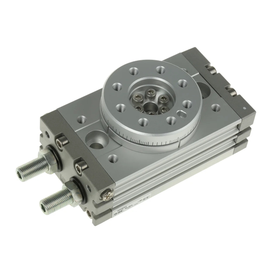
- Page 1 Doc. No. DIU-10D00-OM002-C PRODUCT NAME Rotary Table MODEL / Series / Product Number...
-
Page 2: Table Of Contents
Contents Safety Instructions Outline How to order Specifications Weight Effective torque Internal construction and parts MSQ10 to 50 Made to Order Basic circuit Circuit structure Recommended models Mounting Load restrictions Unit used as flange mount Rotation direction and rotation angle Rotating range example Special angle adjustment tool Angle adjustment using the special tool... -
Page 3: Safety Instructions
Safety Instructions These safety instructions are intended to prevent hazardous situations and/or equipment damage. These instructions indicate the level of potential hazard with the labels of “Caution,” “Warning” or “Danger.” They are all important notes for safety and must be followed in addition to International Standards (ISO/IEC) , and other safety regulations. - Page 4 Safety Instructions Caution 1.The product is provided for use in manufacturing industries. The product herein described is basically provided for peaceful use in manufacturing industries. If considering using the product in other industries, consult SMC beforehand and exchange specifications or a contract if necessary. If anything is unclear, contact your nearest sales branch.
- Page 5 Design / Selection Warning 1. Confirm the specifications. Products represented in this catalog are designed only for use in compressed air systems. Do not operate at pressures or temperatures, etc., beyond the range of specifications, as this can cause damage or malfunction. (Refer to the specifications.) Please contact SMC when using a fluid other than compressed air.
- Page 6 12. Select a speed within the product’s allowable energy value. If the product’s kinetic energy of the load exceeds the allowable value, it could damage the product, and cause a hazard to humans and damage the machinery and equipment. 13. Provide a shock absorber if the kinetic energy that is applied to the product exceeds the allowable value.
- Page 7 Mounting Warning 1. Operation manual Install the product and operate it only after reading the operation manual carefully and understanding its contents. Also, keep the manual in a location where it can be referred to as necessary. 2. Ensure sufficient space for maintenance activities. When installing the products, allow access for maintenance.
- Page 8 12. Place an external stopper in a position that is away from the rotating table. If the stopper is placed near the rotating table, the torque that is generated by the product itself will cause the reaction force which is directed to the stopper to be redirected and applied to the rotating table. This will lead to the breakage of the rotating table and bearing.
- Page 9 Caution 1. Do not use organic solvent to wipe the area of the name plate that shows the model. It will erase what is indicated on the name plate. 2. Do not hit the rotating table by securing the body or hit the body by securing the rotating table.
- Page 10 2. For products with shock absorbers, when the shock absorber stops motion before reaching the stroke end using a stopper mechanism with the objective of shortening tact time be sure the shock absorber is stopped in a position where it has adequately absorbed the kinetic energy.
- Page 11 Operating Environment Warning 1. Do not use in an atmosphere having corrosive gases, chemicals, sea water, water, steam, or where there is direct contact with any of these. Refer to the construction for information on the rotary table material. 2. Do not expose the product to direct sunlight for an extended period of time. 3.
- Page 12 Auto Switches Precautions Design / Selectio Warning 1. Confirm the specifications. If the product is used with excess load applied or beyond the specification range, this may cause the product to break or malfunction. We do not guarantee against any damage if the product is used outside of the specification range.
- Page 13 7. Keep wiring as short as possible. <Reed> As the length of the wiring to a load gets longer, the rush current at switching ON becomes greater, and this may shorten the product’s life. (The switch will stay ON all the time.) 1) Use a contact protection box when the wire length is 5m or longer.
- Page 14 10. Pay attention to leakage current. <2-wire type> Current (leakage current) flows to the load to operate the internal circuit even when in the OFF state. > Operating current of load (OFF condition) Leakage current If the criteria given in the above formula are not met, it will not reset correctly (stays ON).Use a 3-wire switch if this specification will not be satisfied.
- Page 15 6. Check the actual actuation status and adjust the auto switch mounting position. According to the installation environment, the rotary table may not operate even at its proper mounting position. Even when setting at a midpoint of the stroke, check the actuation status and make the adjustment in the same manner.
- Page 16 7. Avoid incorrect wiring. <Reed> A 24 VDC auto switch with indicator light has polarity. The brown lead wire or terminal No.1 is (+), and the blue lead wire or terminal No.2 is (-). 1) If connections are reversed, an auto switch will operate, however, the light emitting diode will not light Also, take note that a current greater than that specified will damage a light emitting diode and it will no longer operate.
- Page 17 2. Do not use in an environment where the auto switch will be continually exposed to water. Although auto switches satisfy IEC standard IP67 construction expect some models (D-A3□, A44□, G39□, K39□, RNK, RPK) do not use auto switches in applications where continually exposed to water splash or splay.
- Page 18 Caution 1. Perform the following maintenance periodically in order to prevent possible danger due to unexpected auto switch malfunction. 1) Secure and tighten auto switch mounting screws. If screws become loose or the mounting, position is dislocated, retighten them after readjusting the mounting position.
-
Page 19: Outline
Outline This operation manual explains “Rack and Pinion Type Rotary table”. When using the product, load (moment of inertia), rotation time and other factors have to be considered. So, confirm the specification of the product prior to use. How to order -... -
Page 20: Specifications
Specifications Table 1. Specifications Size Fluid Air (non-lube) With cushion pad 1MPa Maximum operating With internal shock pressure 0.6MPa absorber Minimum operating pressure 0.1MPa Ambient and fluid temperature 0 to 60°C (no freezing) Cushion Cushion pad or Shock absorber With cushion pad 0.007J 0.025J 0.048J... -
Page 21: Weight
Weight Table 3. Size With adjustment bolt 1500 Basic Type With internal shock absorber 1130 1810 * Values excluding the weight of auto switch *For order made products, add the weight shown in Table 4 to the weight of the basic type. Table 4. -
Page 22: Internal Construction And Parts
Internal construction and parts MSQ10 to 50 Product label M5 Plug assembly Steel ball Steel ball Steel ball Snap ring Seal washer Low head hexagon socket head cap screw 4pcs. for size 20, 30, 50 Ultra low head cap screw Bearing Bearing Piston seal... -
Page 23: Made To Order
Made to Order With interchangeable table and interchangeable plate With interchangeable table With interchangeable plate Cross recessed round head screw for precision For -A, -C Interchangeable plate For -A, -C Parallel pin For -A, -B Hexagon socket head cap screw For -A, -B Interchangeable table For -A, -B... -
Page 24: Basic Circuit
Basic circuit Circuit structure The standard circuit for operating a rotary cylinder with an air filter, regulator, solenoid valve and speed controller is shown in Figure 1 below. Regulator Speed controller Air filter Solenoid valve Rotary actuator Fig.1 Basic circuit Recommended models Recommended models for the standard circuit in Figure 1 are shown in Table 5 below. -
Page 25: Mounting
Mounting Load restrictions Set the load and moment to be applied to the table within the allowable values shown in the table below. (Values exceeding the allowable range will cause excessive play, reduce accuracy, and shorten service life.) Fig. 2 Table 6. -
Page 26: Rotation Direction And Rotation Angle
Rotation direction and rotation angle ・When the cylinder is pressurized from port B, the table rotates clockwise. ・To obtain the desired rotation angle, the rotation ends can be set within the range shown in the diagram by regulating the adjustment bolt or shock absorber. Fig. -
Page 27: Rotating Range Example
Rotating range examples Various rotation ranges are possible as shown in the drawings below using adjustment bolts A and B. (The drawings show the rotation range of the positioning pin hole.) The rotation angle can also be set on a type with internal shock absorber. Fig. -
Page 28: Special Angle Adjustment Tool
Special angle adjustment tool If it is difficult to adjust the angle with normal tools due to the installed condition, use the special tool specified below. Table 9 shows the part number of the special angle adjustment tool and Table 10 shows the dimensions of the special tool. -
Page 29: Piping
Also, if pipe tape is used, leave 1.5 to 2 thread ridges exposed at the end of the threads. Sealant tape Winding direction Expose approx. 2 threads Fig. 9 Wrapping of pipe tape Air supply Air supplied to the rotary actuator shall be cleaned by the filter. MSQ series is lubrication free. - 28 -... -
Page 30: Setting Of Rotation Time
Setting of rotation time It is necessary to calculate the inertial load and kinetic energy in the application prior to setting the speed of the actuator. The inertial load generated in the application may be high even if the torque required in the application is low, this may lead to damage to the internal components of the actuator. -
Page 31: Calculation Formulae For Moment Of Inertia
Calculation formulae for moment of inertia I: Moment of inertia [ kg・m ] m: Load mass [ kg ] 1. Thin shaft 6. Thin round plate Position of rotational axis: Perpendicular to the Position of rotational axis: Through the center of shaft through the center of gravity diameter ・... -
Page 32: Kinetic Energy
Kinetic energy Table 12 shows the allowable kinetic energy of the rotary table. The end angle speed ω is obtained by: Table 12. Allowable kinetic energy Allowable kinetic energy Size With internal shock With cushion pad θ: Rotation angle [ rad ] absorber t: Rotation time [ s ]... -
Page 33: Auto Switch
Auto switch The rotary table has a magnet mounted on its piston and an auto switch on the outside of the body to detect the piston position (table position). Rotary tables have a short piton stroke, so detection should be done at the stroke end. -
Page 34: Auto Switch Proper Mounting Position At Rotation End
Auto switch proper mounting position at rotation end Adjustment bolt Adjustment bolt Table 14. Dimension E [mm] Adjust- Shock Size ment bolt absorber Magnet Operation range at optimum set position (Lm/2) Fig. 13 Most sensitive position Auto switch operating range Lm Table 15. -
Page 35: Maintenance And Inspection
Maintenance and Inspection Periodic inspection is necessary for optimum use. Generally, annual inspection is recommended for the rotary table. Even if no problem is found, seal parts replacement is recommended every three years. It is highly possible that the actuator is operated out of specification when the components like table pinion, piston, bearing are broken. - Page 36 ■Disassembly procedure Basic type Made to Order Fig. 14 (1) Loosen the hexagon socket head cap screws and remove the interchangeable table and parallel pin. *Made to Order -A, -B only Hexagon socket head cap screw Parallel pin Interchangeable table Fig.
- Page 37 (3) Loosen ultra low head cap screw to remove the bearing retainer. Ultra low head cap screw Bearing retainer Fig. 17 (4) Pull out the table pinion from the body. Table pinion assembly Fig. 18 (5) Loosen the low head hexagon socket head bolt to remove the end cover assembly. Low head hexagon socket head cap screw Fig.
- Page 38 (6) Pull out the 2 piston assemblies by hooking the piston rack. (Piston assemblies are visible from the hole for the assemblies). Piston assembly Fig. 20 (7) Take out the bearing from the body. Bearing Body Fig. 21 - 37 -...
- Page 39 ■Assembly procedure (1) Clean each component sufficiently before assembly to prevent a dust from sticking to them. Apply the grease which is included in the seal kit to each part shown in Table 17 The correct amount of grease to be applied should be enough so there is a thin film on the surface of components which is shiny to the eye.
- Page 40 End cover assembly Gasket Adjustment bolt assembly or shock absorber M5 Plug Assembly Compact hexagon nut End cover Seal washer Fig. 24 Recommended tightening torque [N・m] Size Adjustment bolt M5 plug assembly Shock absorber 1.00 to 1.67 20,30 1.88 to 3.14 1.00 to 1.50 6.48 to 10.8 (2) Insert the piston assembly into the body assembly.
- Page 41 (3) Hold the piston in place and install the pinion gear on the piston. Figure 25 shows the piston position and Figure 26 shows the pinion gear assembly angle. Size 10・20 Size 30・50 Fig. 26 Position of body pin hole Position of table pinion assembly pin hole...
- Page 42 (4) Mount the table pinion and bearing retainer on the body. Pay attention to the direction of the bearing retainer. Ultra low head cap screw Bearing retainer Body Fig. 28 Recommended tightening torque Size [N・m] 0.56 to 1.00 20,30 1.94 to 3.50 2.78 to 5.00 Fig.
- Page 43 (6) Mount the interchangeable plate to the body. Pay attention to the direction of the Interchangeable plate. *Made to Order -A, -C only Positioning pin hole Interchangeable plate Cross recessed round head screw for precision equipment Recommended Size tightening torque[N・m] Fig.
-
Page 44: Troubleshooting
Troubleshooting Problem Possible cause Solution Supply pressure is not applied Correctly set the regulator at the supply correctly. pressure side. The directional switching Correctly apply a signal to the directional valve (such as a solenoid switching valve (such as a solenoid valve). valve) does not switch. - Page 45 Problem Possible cause Solution Air leakage from the The seal parts need to be replaced. Piston seal is worn out. table Contact SMC. Replace the rotary table with the new one. Excessive kinetic energy was After that, take the measures below. ・Calculate the kinetic energy applied to the applied to the rotary table.
- Page 46 Revision history 4-14-1, Sotokanda, Chiyoda-ku, Tokyo 101-0021 JAPAN Tel: + 81 3 5207 8249 Fax: +81 3 5298 5362 https://www.smcworld.com Note: Specifications are subject to change without prior notice and any obligation on the part of the manufacturer. © 2019 SMC Corporation All Rights Reserved...
Need help?
Do you have a question about the MSQ Series and is the answer not in the manual?
Questions and answers