
Related Manuals for SMC Networks MSQ Series


Summary of Contents for SMC Networks MSQ Series
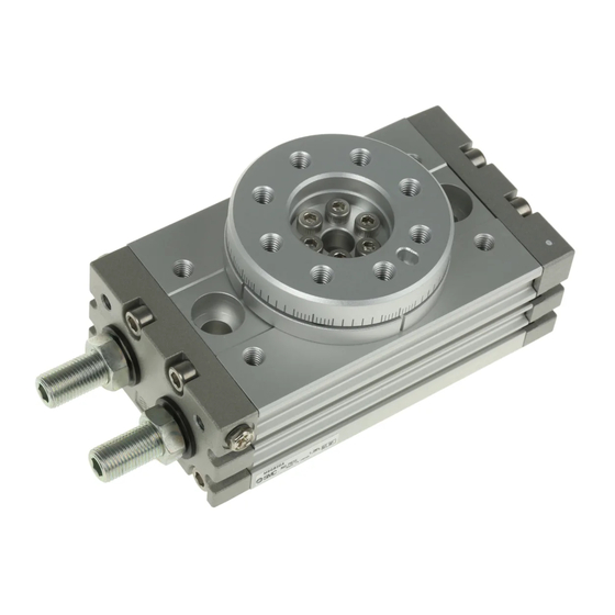
- Page 1 Doc. no.MSQB-OM00004-E PRODUCT NAME Rotary Table MODEL / Series / Product Number MSQ10 to 200()
-
Page 2: Table Of Contents
Contents Safety Instructions Outline Specifications Mass Effective torque Internal construction and parts Basic circuit Circuit structure Recommended models Mounting Load restrictions Flange application Direction and Angle of Rotation (Adjusting bolt, Internal shock absorber type) Rotating range examples (Adjusting bolt, Internal shock absorber type) Rotating direction and rotating angle (External shock absorber type) Piping Air supply... -
Page 3: Safety Instructions
Safety Instructions These safety instructions are intended to prevent hazardous situations and/or equipment damage. These instructions indicate the level of potential hazard with the labels of “Caution,” “Warning” or “Danger.” They are all important notes for safety and must be followed in addition to International Standards (ISO/IEC) , and other safety regulations. - Page 4 Safety Instructions Caution 1.The product is provided for use in manufacturing industries. The product herein described is basically provided for peaceful use in manufacturing industries. If considering using the product in other industries, consult SMC beforehand and exchange specifications or a contract if necessary. If anything is unclear, contact your nearest sales branch.
- Page 5 Design / Selection Warning ① Confirm the specifications. Products represented in this catalog are designed only for use in compressed air systems. Do not operate at pressures or temperatures, etc., beyond the range of specifications, as this can cause damage or malfunction. (Refer to the specifications.) Please contact SMC when using a fluid other than compressed air.
- Page 6 ⑫ Select a speed within the product’s allowable energy value. If the kinetic energy of the load exceeds the allowable value, it could damage the product, and cause a hazard to humans and damage the machinery and equipment. ⑬ Provide a shock absorber if the kinetic energy that is applied to the product exceeds the allowable value.
- Page 7 Mounting Warning ① Operation manual Install the product and operate it only after reading the operation manual carefully and understanding its contents. Also, keep the manual in a location where it can be referred to as necessary. ② Ensure sufficient space for maintenance activities. When installing the products, allow access for maintenance.
- Page 8 Precautions when Using External Stoppers ・ Be sure to install external stoppers in the proper places. Installation in the wrong place can result in equipment breakage, which could damage other equipment or cause human injury. Install the stopper at a sufficient The external stopper becomes a If an external stopper is installed distance from the rotating shaft.
- Page 9 Caution ① Do not use organic solvent to wipe the area of the name plate that shows the model. It will erase what is indicated on the name plate. ② Do not hit the rotating table by securing the body or hit the body by securing the rotating table. These actions could cause the table to bend or damage the bearing.
- Page 10 Lubrication Warning ① This product should be used without lubrication. Although it will operate even if it is lubricated, it could lead to sticking or slipping. Air Supply Warning ① Type of fluids Please consult with SMC when using the product in applications other than compressed air. ②...
- Page 11 Operating Environment Warning ① Do not use in an atmosphere containing corrosive gases, chemicals, sea water, water, steam, or where there is direct contact with any of these. Refer to the construction diagram for information on the materials used in the rotary table. ②...
- Page 12 Auto Switches Precautions Design / Selectio Warning ① Confirm the specifications. Read the specifications carefully and use this product appropriately. The product may be damaged or malfunction if it is used outside the range of specifications of current load, voltage, temperature or impact.
- Page 13 ④ Do not use a load that generates surge voltage. If a surge voltage is generated, discharge may be generated at the contact, possibly reducing the product life. If driving a load such as a relay that generates a surge voltage. <Reed>...
- Page 14 Mounting / Adjustment Warning ① Do not drop or bump. Do not drop, bump or apply excessive impacts (300m/s or more for reed auto switches and 1000m/s or more for solid state auto switches) while handling. Although the body of the auto switch may not be damaged, the inside of the auto switch could be damaged and cause malfunction.
- Page 15 ⑤ Do not allow short-circuit of loads. <Reed> If the power is turned ON with a load in a short circuit condition, the switch will be instantly damaged because of excess current flow into the switch. <Solid state> PNP output type auto switches do not have built-in short circuit prevention circuits. If a load is short circuited, the auto switch will be instantly damaged as in the case of reed auto switches.
- Page 16 Operation Environment Warning ① Never use in an atmosphere with explosive gases. Auto switches are not designed with explosion-proof construction. Never use in an atmosphere containing explosive gas since this may cause a serious explosion. Please contact SMC concerting ATEX compliant products. Caution ①...
- Page 17 Maintenance Warning ① Removal of equipment, and supply/exhaust of compressed air. Before any machinery or equipment is removed, first ensure that the appropriate measures are in place to prevent the fall or erratic movement of driven objects and equipment, then cut off the electric power and reduce the pressure in the system to zero.
-
Page 18: Outline
Outline This operation manual explains “Rack and Pinion Type Rotary Cylinder”. When using the product, load (moment of inertia), rotation time and other factors have to be considered. So, confirm the specification of the product prior to use. Specifications Table 1. Specifications Size Fluid Air (non-lube) -
Page 19: Mass
- 17 - Table 2. Minimum rotation angle that will not allow decrease of energy absorption ability Internal shock absorber type Size Minimum rotation angle that will not allow decrease of energy 52° 43° 40° 60° 71° 62° 82° absorption ability Table 3. -
Page 20: Internal Construction And Parts
Internal construction and parts MSQ10~50 (Adjustment bolt type, Internal shock absorber type) Product label Plug Seal washer Parallel pin Hexagon socket head cap screw Hexagon socket head cap screw Hexagon thin socket head bolt (Size10 Cross recessed round head screw) Round head no.0 Philips screw Bearing High precision type:2 (angular duplex bearing) - Page 21 MSQB70~200 (Adjustment bolt type, Internal shock absorber type) Product label Plug Steel ball Seal washer Parallel key Type CS retaining ring Hexagon socket head cap screw Hexagon socket head cap screw Hexagon socket head cap screw Round head no.0 Philips screw Bearing Needle bearing Piston seal...
- Page 22 MSQ10~50 (External shock absorber type) Product label Shock absorber Plug Hexagon nut Parallel pin Hexagon socket head cap screw 90°:4 pcs., 180°:2 pcs. Hexagon socket head cap screw Hexagon socket head cap screw Hexagon socket head cap screw Hexagon thin socket head bolt (Size10 Round head Philips screw ) Round head no.0 Philips screw Bearing...
-
Page 23: Basic Circuit
Basic circuit Circuit structure The standard circuit for operating a rotary cylinder with an air filter, regulator, solenoid valve and speed controller is shown in Figure 1 below. Regulator Speed controller Air filter Solenoid valve Rotary actuator Fig. 1 Basic circuit Recommended models Recommended models for the standard circuit in Figure 1 are shown in Table 5 below. -
Page 24: Mounting
Mounting Load restrictions Set the load and moment to be applied to the table within the allowable values shown in the table below. (Values exceeding the allowable range will cause excessive play, reduce accuracy, and shorten service life.) Fsa Fsb Fig. -
Page 25: Direction And Angle Of Rotation (Adjusting Bolt, Internal Shock Absorber Type)
Direction and Angle of Rotation (Adjusting bolt, Internal shock absorber type) ・When the cylinder is pressurized from port A, the table rotates clockwise. ・To obtain the desired rotation angle, the rotation ends can be set within the range shown in the diagram by regulating the adjustment bolt. -
Page 26: Rotating Range Examples (Adjusting Bolt, Internal Shock Absorber Type)
Rotating range examples (Adjustment bolt, Internal shock absorber type) Various rotation ranges are possible as shown in the drawings below using adjustment bolts A and B. (The drawings show the rotation range of the positioning pin hole.) Fig. 6 - 25 -... -
Page 27: Rotating Direction And Rotating Angle (External Shock Absorber Type)
Rotating direction and rotating angle (External shock absorber type) ・When the cylinder is pressurized from port A, the table rotates clockwise. ・To obtain the desired rotation angle, the rotation ends can be set within the range shown in the diagram by regulating the shock absorber. -
Page 28: Piping
Note) ・Although the rotating angle of external absorber type can be made smaller by screwing in a shock absorber, do not make it smaller than the minimum rotating angle of 84° (90° specification) and 174° (180° specification). This will increase the deflection angle on the working face of the shock absorber’s piston rod and arm, causing damage to the shock absorber. -
Page 29: Setting Of Rotation Time
Setting of rotation time Even if the torque that is required by the load in the rotation movement is small, the internal parts could become damaged depending on the inertia of the load. Therefore, select an appropriate model for your application by taking the load’s moment of inertia, kinetic energy, and rotation time into consideration. -
Page 30: Calculation Formulae For Moment Of Inertia
Calculation formulae for moment of inertia I: Moment of inertia [ kg・m ] m: Load mass [ kg ] 6. Thin round plate 1. Thin shaft Position of rotational axis: Through the center of Position of rotational axis: Perpendicular to the diameter shaft through the center of gravity I = m... -
Page 31: Kinetic Energy
Kinetic energy Table 10 shows the allowable kinetic energy of the rotary table. Here, the angular speed ωcan be found from the formula below. Table 10 Allowable kinetic energy 2 ω= Allowable kinetic energy J External Internal Size shock absorber Adjusting bolt θ: Rotation angle [ rad ]... -
Page 32: Auto Switch Type For Rotary Table
Auto switch type for rotary table The rotary table has a magnet mounted on its piston and an auto switch on the outside of the body to detect the piston position (table position). Rotary tables have a short piton stroke, so detection should be done at the stroke end. - Page 33 Table 12 Solid state auto switch specification (D-M9□) Internal Auto switch Power Current Load Load Current Applicable Output voltage part no. voltage consumption voltage current leakage load drop D-M9N D-M9NV DC28V D-M9NW type or less At 10mA D-M9NWV DC5・12・ 0.8V or 100µA or Relay 10mA...
-
Page 34: Mounting Of Auto Switch
Mounting of auto switch Use a watchmaker’s screwdriver of grip diameter 5 to 6mm to tighten the auto switch mounting screws to a tightening torque of D-M9:0.05 to 0.15N・m, D-A9:0.10~0.20 N・m. Use the designated slotted set screws. Fig. 11 Proper auto switch mounting position at rotation end Operation range at optimum set position (Lm/2) Most sensitive position... -
Page 35: Internal Structure And Operation Principle
Internal structure and operation principle Fig. 13 When switch A is turned on and pressure is supplied in the direction indicated by the arrows in Fig. 13, the piston moves and the table rotates clockwise. At this point, magnet A goes out of switch A's operation range to turn off switch A. Then the piston moves further, and the magnet goes into switch B's operation range to turn on switch B. -
Page 36: External Stopper
* Caution for using external stopper Angle adjustment is available for MSQ series rotary actuator. When using an external stopper, set in a position so that that the adjusting bolt does not collide into the piston. -
Page 37: Maintenance And Inspection
Maintenance and Inspection In order to use the rotary table in an optimal condition, it is necessary to perform maintenance regularly depending on the operating conditions. It is preferable to perform maintenance of the rotary table once a year in general. Even if no problem is found, seal parts replacement is recommended every three years. Note that if mechanical components such as pinion, rack, bearing etc. - Page 38 ■Disassembly procedure (1) Loosen hexagon socket head cap screw and pull out the table. Loosen hexagon thin socket head bolt (Size 10 Cross recessed round head screw Size 70, 100, 200 Hexagon socket head cap screw) to remove the bearing retainer. (2) Pull out the pinion and the bearing from the body.
- Page 39 ■Assembly procedure (1) Clean each component sufficiently before assembly to remove any dust etc. Apply the grease provided in the seal set to each part shown in Table 14. As a guideline, apply enough grease to make the surface shiny. Table 14.
- Page 40 Cover assembly Size 70・100・200 Cover Size 10・20・30・50 Seal Plate Gasket (Cover) O-ring Round head no.0 Philips screw Fig. 18 End cover assembly Size 10・20・30・50 (Adjust bolt, Internal shock absorber type) Gasket (End cover) Compact hexagon nut Adjustment bolt Plug End cover Seal washer Size 70・100・200 Size 10・20・30・50...
- Page 41 (2) Insert the piston assembly into the body assembly. In this case, the piston seals pass through the cylinder opening, so install the seals into the opening while squeezing them to prevent the seals from being damaged. Pay attention to the insertion direction of the piston and the body as they are specified. (Figure 20) Fig.
- Page 42 (4) Install the bearing, bearing holder and table on the body. Hexagon socket head cap screw Table Size 10 Cross recessed round head screw Size 20・30・50 Hexagon thin socket head bolt Size 70・100・200 Bearing retainer Hexagon socket head cap screw Bearing Body Fig.
-
Page 43: Troubleshooting
Troubleshooting Problem Possible cause Solution Supply pressure is not applied Correctly set the regulator at the supply correctly. pressure side. directional switching Correctly apply a signal to the directional valve (such as a solenoid switching valve (such as a solenoid valve). valve) does not switch. - Page 44 Problem Possible cause Solution Air leakage from the The seal parts need to be replaced. Contact Piston seal is worn out. table SMC. Replace the rotary table with the new one. After that, take the measures below. Excessive kinetic energy was applied to the rotary table.
- Page 45 Revision history A: Corrected the mounting position of the auto switch. B: Corrected product mounting bolt size. C: Erratum Correction. D: Fully revised following product review. E: Added a note of caution. 4-14-1, Sotokanda, Chiyoda-ku, Tokyo 101-0021 JAPAN Tel: + 81 3 5207 8249 Fax: +81 3 5298 5362 http://www.smcworld.com Note: Specifications are subject to change without prior notice and any obligation on the part of the manufacturer.
Need help?
Do you have a question about the MSQ Series and is the answer not in the manual?
Questions and answers