
Related Manuals for Gossen MetraWatt LonWorks U128-W1 Series


Summary of Contents for Gossen MetraWatt LonWorks U128-W1 Series
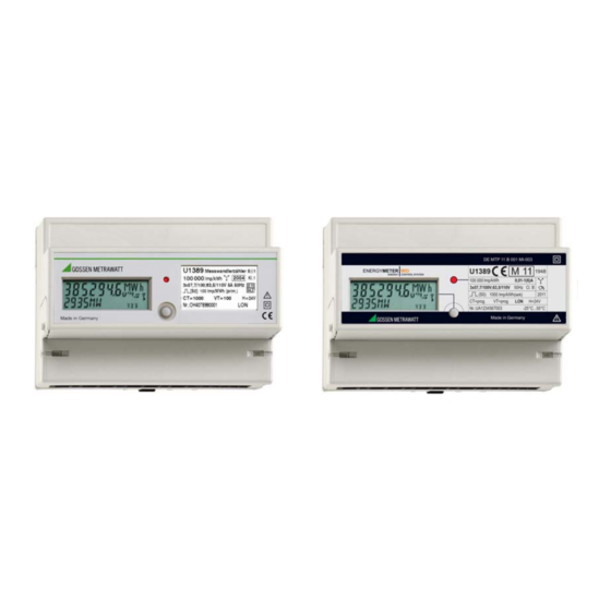
- Page 1 Interface Description U128x-W1 U138x-W1 Electronic Active and reactive Energy Meters 3-349-312-03 with LON Interface 6/6.11...
-
Page 2: Table Of Contents
Table of Contents Wiring Page The most commonly utilized transmission medium for industrial and building management applications is twisted pair copper General Information Regarding the LON Bus ....2 cable, which is used together with the electrically isolated FTT-10A transceiver. Both of the conductors can be connected to Overview ................ -
Page 3: Maximum Cable Lengths
Maximum Cable Lengths Network Interface Cable Type / Bus Topology Free Topology Network Variables Cable Designation (bus terminator at both ends) (bus terminator at one end) Measured quantities and energy meter status information JY (ST) Y 2 ea. 2 x 900 m 500 m, max. -
Page 4: Units And Resolutions
Power meter – powerMeter ObjectId: 2 Energy meter – energyMeter ObjectId: 4 Index Network Variable Data Type Description Network Variable Data Type Description Index Active Power nviEnergyClr SNVT_switch Reset nvoWhTot nvoWatTot SNVT_power_f Total active power, all 3 phases nvoWhTot SNVT_elec_whr_f Total active energy, all 3 phases nvoWat1 SNVT_power_f... -
Page 5: Functions Of The Energy Meter Object
Voltmeter – voltMeter ObjectId: 3 4.3.3 Energy Meter for Active and Reactive Energy Voltage VT at U3 (100 V) Display at U5 ... U7 Unit Resolution U128x xxx.x V 0.1 V 1 ... 4 xxx.x V 0.1 V 5 ... 40 2 ... -
Page 6: Control And Display Functions
Control and Display Functions The neuron ID appears in an additional menu entry. The service pin message is transmitted by pressing and holding the key. Overview of Parameter Setting (excerpt from operating instructions 3-349-275-15 or 3-349-618-15, expanded to include LON parameter setting) Standard display Auto... -
Page 7: S0 Pulse Rate
Installing the Meter Error Messages The meter can be installed to a LON network by manually entering the neuron ID, or by triggering the service pin message. Message via Cause / Remedy Device Display LON interface Node object Object Id: 0 LON Node Status –... -
Page 8: Configuring The Meter With The Lns Plug-In And Displaying Current Measured Values
Configuring the Meter with the LNS Plug-In Registering and Starting the LNS-Plug-In and Displaying Current Measured Values The following steps must be completed before the plug-in can be The meter can be fully configured via the LON interface. An LNS started: plug-in is available on the Internet to this end. -
Page 9: Descriptions Of Tab Cards For The Lns Plug-In
4.7.2 Descriptions of Tab Cards for the LNS Plug-In The Node Tab Card – NodeObject Tab Card with Measurement Data Overview – Monitor In addition to quantities in the 3-phase system, the Monitor tab card also include meter type and features, manufacturing serial number, software version and the Location Label assigned by the user. - Page 10 Current Measurement Tab Card – amMeter Voltage Measurement Tab Card – voltMeter Left-Hand Column Left-Hand Column Conditions for Automatic Network Variable Update Conditions for Automatic Network Variable Update Conditions for automatic transmission of network variables are Conditions for automatic transmission of network variables are selected here.
- Page 11 Power Measurement Tab Card – powerMeter Energy Measurement Tab – energyMeter Conditions for Automatic Network Variable Update Left-Hand Column Conditions for Automatic Network Variable Update Conditions for automatic transmission of network variables are selected here. A new value is not transmitted until deviation in Conditions for automatic transmission of network variables are comparison with the last value is greater than or equal to selected here.
-
Page 12: Product Support
Product Support If required please contact: GMC-I Messtechnik GmbH Product Support Hotline Phone: +49 911 8602-500 Fax: +49 911 8602-340 e-mail: support@gossenmetrawatt.com Edited in Germany • Subject to change without notice • PDF version available on the Internet Phone +49 911 8602-111 GMC-I Messtechnik GmbH +49 911 8602-777 Südwestpark 15...
Need help?
Do you have a question about the LonWorks U128-W1 Series and is the answer not in the manual?
Questions and answers