Table of Contents
Advertisement
Advertisement
Table of Contents

Related Manuals for Nederman FilterMax C 25


Summary of Contents for Nederman FilterMax C 25
- Page 1 C 25 INSTRUCTION MANUAL ENGLISH C 25 144161(06) 2013-10-22...
-
Page 2: Table Of Contents
C 25 List of contents sida CE, Declaration of conformity IMPORTANT! Safety information Delivery check Technical data Dimensions Mounting instructions Installation Compressed air connection Electrical installation 7 - 8 Earth control measuring Fan diagram Applications Duct dimensioning / System installation Operating Operating description Starting the system... -
Page 3: Ce, Declaration Of Conformity
To maintain this status all installation, repair and mainte- nance work must be carried out by qualified personnel using only original spare parts. Contact your nearest authorised dealer or AB Ph. Nederman & Co. for advice on technical service or if you require spare parts. Declaration of conformity We, AB Ph. -
Page 4: Technical Data
C 25 TECHNICAL DATA Filtration 99% or 99,9 % (PTFE-filter) at 0,5 µm (after some time in operation) Filter area 4 x 12 = 48 m (Poly Web filter) 4 x 10 = 40 m (Poly Web antistatic filter) Filter material PTFE Impregnated spun bound polyester (PW NS) PTFE membrane laminated to spun bound polyester (PW PTFE) Aluminium spun bound polyester (PWA) -
Page 5: Mounting Instructions
It should be located with consideration for easy hand- ling of the collected dust and for convenience of service and maintenance. FilterMax C 25 is usually installed on a reinforced concrete foundation. However, installation on another structure is also possible. When calculating... -
Page 6: Compressed Air Connection
C 25 COMPRESSED AIR CONNECTION Compressed air tank Water drain valve Sevice valve (accessory) IMPORTANT! • The compressed air supply pressure has to be = 0,5 - 0,6 MPa (5 - 6 bar / 72 - 87 psi). Compressed • The compressed air shall have a dew point air connection below the minimum temperature at which the system is ment to be used. -
Page 7: Electrical Installation
All electrical work must be done by a qualified electrician ac- cording to local regulations. WARNING! Connect FilterMax C 25 to the mains and connect other compo- Risk of personal injury! nents and accessories according to wiring diagram on this page. - Page 8 C 25 or nC or nO Motor protector, fan Push the P-button. Activated input: no. 2 Set OFF, nC or nO with the 0/1-button. Blinking NO is preset at delivery. or nC or nO High dust level Push the P-button. Activated input: no.
-
Page 9: Earth Control Measuring
• In some countries the purified air must not be recycled in explosive contaminations. the workshop if FilterMax C 25 is used to separate welding Explosive dusts are dry organic dusts and some fume or some contaminations that may be a health hazard. -
Page 10: Duct Dimensioning / System Installation
C 25. The following duct diameters can be used for • Use larger diameters on the clean side to the connection to FilterMax C 25: Ø 250 mm for the inlet reduce pressure losses. and Ø 315 mm for the outlet. -
Page 11: Operating Operating Description
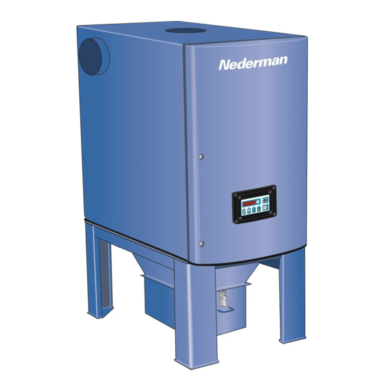
C 25 OPERATING DESCRIPTION The contaminated air is led Valve with Outlet duct Built-in connection box through the inlet and then distribu- cleaning pipe with transformer, relay and ted downwards towards the filter motor protector. cartridges. Built-in fan The filter media in the cartridges Compressed collects the... -
Page 12: Starting
MONITORING SYSTEM, SETTINGS CLEANING DURING OPERATION FilterMax C 25 is in its standard design equipped with a fully auto- matic compressed air cleaning of the filter cartridges. A piping sys- tem directs, by a system of solenoid valves, air pulses of 100 ms into the filter cartridges. - Page 13 OFF: When using remote start there is no automatic restart when a fault has been rectified. The remote started mashine must be stopped and the FilterMax C 25 must be reset by one push on the start button before a new remote start can be done.
-
Page 14: Monitoring System, General Descriptions
C 25 MONITORING SYSTEM, GENERAL DESCRIPTIONS The LED:s can indicate the following: 1, 2, 3______ green fixed light: All functions normal and correct 1, 2, 3______ green fixed light alternating with blinking red: The system operates. Incorrect function has been rectified (alarm memory) 1, 2, 3______ red fixed light: Incorrect function which requires investigations. -
Page 15: Monitoring System, Fault Indications
0.5 - 0.6 MPa (5 - 6 bar / 72 - 87 psi). • Check the pause time (factory set at 60 s, see page 12). The door is open and FilterMax C 25 will not start. r E A or another digit... - Page 16 C 25 EMPTYING THE DUST CONTAINER IMPORTANT! Empty the dust container when it is approximately 70 % full. Do not let it overfill. It can cause poor filter performance and cause an extensive clean up work due to overflow of dust Use protection goggles, breathing when removing the container.
- Page 17 The filter cartridges are replaceable. They should be replaced if the outer surfaces are damaged or if the air flow through FilterMax C 25 is insufficient due to saturation of the filter cartridges despite repeated cleaning. Switch off the FilterMax C 25.
- Page 18 (approx. 15 min.) whereafter the system can be pressurised. Possible faults FilterMax C 25 will not start. Control questions Is text dOOr on the display? Actions Check that the access door is closed and the door switch not is damaged.
- Page 19 40 % of its possible air volume. Check in the following way: • Loosen the fixing screws on the access door. • Start the FilterMax C 25. • Stop the FilterMax C 25. • Open the access door and check through the fan inlet the impeller rotation direction.
- Page 20 C 25 A valve is not operating correctly (but there are functioning valves). Does the display on the control box IMPORTANT! show Err + a digit? Turn off the compressed air supply with the service valve (ac- cessory) before doing any work Is the air temperature below 0 °C ? on the cleaning system.
-
Page 21: Spare Parts
1 Filter cartridges, 4-pack 8 Transformer * A. Part No. and Control No. (see page 22) 9 Motor protector * (see FilterMax C 25 identification plate) 2 Cover with display and 10 Pilot valve B. The spare part’s name and number circuit card... -
Page 22: Accessories Accessories
C 25 SPARE PARTS REPLACEMENT CARTRIDGES (4-PACK) PW NS-95-12-4/W3 PTFE impregnated (Non-Stick), spun bound polyester. Suitable for fumes and fine to medium dust. Efficiency: 99 % at 0,5 µm (after some time in operation) Filter area: 12 m Washable BIA class M PW PTFE-95-12-4 PTFE membrane, laminated to spun bound polyester. -
Page 23: Installation Protocol
INSTALLATION PROTOCOL, PAGE 1 If controls give results (for example measured values) which differ much from earlier results, this must be understood as a warning signal and lead to more careful investigations. FilterMax C 25 No. Date Performed by Control points... - Page 24 C 25 INSTALLATION PROTOCOL, PAGE 2 Date FilterMax C 25 No. Performed by Control points Result Result Result Note 6. Earth control measurement (page 9) GND - Filter unit GND - Door GND - Dust container GND - Filter cartridges (only antistatic) 4.
-
Page 25: Service Protocol
C 25 SERVICE PROTOCOL (page 9, 16 - 17) Date FilterMax C 25 No. Operating hours Performed by Control points Result Result Result Result Result 1. Dust container / Filter regulator A. Empty the dust container (when 70 % full) B. - Page 26 C 25 SERVICE PROTOCOL (page 9, 16 - 17) Date FilterMax C 25 No. Operating hours Performed by Control points Result Result Result Result Result 1. Dust container / Filter regulator A. Empty the dust container (when 70 % full) B.
- Page 27 C 25 SERVICE PROTOCOL (page 9, 16 - 17) Date FilterMax C 25 No. Operating hours Performed by Control points Result Result Result Result Result 1. Dust container / Filter regulator A. Empty the dust container (when 70 % full) B.
- Page 28 C 25 SERVICE PROTOCOL (page 9, 16 - 17) Date FilterMax C 25 No. Operating hours Performed by Control points Result Result Result Result Result 1. Dust container / Filter regulator A. Empty the dust container (when 70 % full) B.
- Page 29 C 25 FilterMax C 25 No. SERVICE NOTES Point no. Date Note...
- Page 30 C 25 www.nederman.com Nederman is represented in: Australia, Austria, Bahrain, Belgium, Brazil, Bulgaria, Canada, China, the Czech Republic, Cyprus, Denmark, Egypt, Estonia, Finland, France, Ger- many, Greece, Hong Kong, Hungary, Iceland, India, Iran, Ireland, Italy, Japan, Korea, Latvia, Lithuania, Malaysia, the Netherlands, Norway, Philippi- nes, Poland, Portugal, Romania, Russia, Saudi Arabia, Serbia &...
Need help?
Do you have a question about the FilterMax C 25 and is the answer not in the manual?
Questions and answers