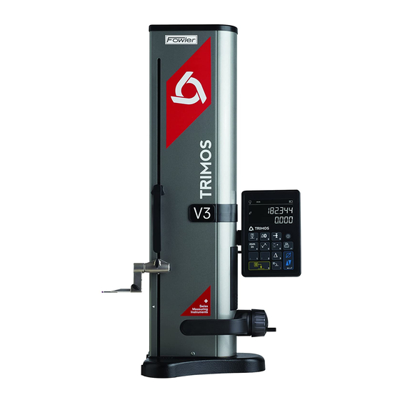
TRIMOS V3 User Manual
Hide thumbs Also See for V3:

Advertisement

USER'S MANUAL
V3 / V4 / V5 / V6 / V8
750 50 0045 03

Advertisement

Table of Contents
loading
Need help?

Need help?

Do you have a question about the V3 and is the answer not in the manual?

Questions and answers

Summary of Contents for TRIMOS V3

  • Page 1 USER’S MANUAL V3 / V4 / V5 / V6 / V8 750 50 0045 03...
  • Page 3 Dear customer, congratulations for choosing a TRIMOS measuring instrument. For more than 40 years, our products have built up an excellent reputation in terms of quality, accuracy and longevity. For full satisfaction with the present product, we recommend to read this user’s manual carefully.
  • Page 4: Table Of Contents

    User's Manual CONTENTS 1. Safety regulations ....................... 4 Important Information ....................4 Security Symbols ......................4 General Warnings ....................... 4 2. Instrument Description ...................... 5 Instrument ........................6 Interfaces/Connectors ....................6 Display ........................6 3. Setting up ..........................7 Packing List ........................ 7 Setting-up ........................
  • Page 5 V3 / V4 / V5 / V6 / V8 7. Data Transfer and Print-out ..................... 30 USB Connection ....................... 30 RS232 Connection ....................31 8. Remote control of the instrument ..................32 Command attributes ....................32 List of commands ..................... 33 9.
  • Page 6: Safety Regulations

    Important Information In order to prevent any damages due to wrong manipulation, please carefully read the following instructions. TRIMOS will not accept any responsibility in case of damages caused by inadequate use not in line with the present manual. Security Symbols...
  • Page 7: Instrument Description

    V3 / V4 / V5 / V6 / V8 INSTRUMENT DESCRIPTION 750 50 0045 03...
  • Page 8: Instrument

    Handle for carriage displacement Transport safety screw for locking of probe suspension (chromium plated) Lower probe holder Insert holder (V3 ÷ V6) Measuring insert Operating handle for the displacement of the instrument Button for activation of air cushion and programmable functions keys (V4 ÷ V6) 10.
  • Page 9: Setting Up

    V3 / V4 / V5 / V6 / V8 SETTING UP 3.1 Packing List The standard packing of the instrument includes the following elements: Instrument with display unit and measuring insert holder Measuring insert Setting gauge Charging unit Protection cover (V5 & V6) User’s manual (V4 ÷...
  • Page 10: Setting-Up

    User's Manual 3.2 Setting-up After unpacking, prepare the instrument as follows: Clean the pads positioned underneath the base using a clean cloth, slightly dampened with alcohol. Position the instrument with care on a clean measuring plate. Mount the display unit on its support using the 2 screws..
  • Page 11 V3 / V4 / V5 / V6 / V8 V3, V4, V5, V6 5. Slide the measuring insert into the holder and lock it, using the knob. Take care to position the eccentric probes correctly. 6. Release the transport safety screw.
  • Page 12: Getting Started

    The manual displacement of the carriage is carried out with (V5 & V6) the help of the handle. This is the only possible displacement mode for V3 & V4. The V8 has a fine adjustment. V5 & V6 Push the handle inwards in order to pass into manual mode.
  • Page 13: Setting Into Operation

    V3 / V4 / V5 / V6 / V8 4.2 Setting into Operation Switch on the instrument by pressing button On/Off during 2 seconds. All segments of the display will light up. Switch off the instrument by pressing the same >...
  • Page 14 User's Manual Use the setting gauge supplied with the instrument to carry out this operation. Note: A different setting gauge may be used. In this case, its dimension must be configured in the set- up menu (§ 9). Move the measuring insert downwards (use the handwheel for the displacement of the measuring carriage) until it touches the surface and an acoustic signal confirms the measurement...
  • Page 15: Main Functions

    V3 / V4 / V5 / V6 / V8 MAIN FUNCTIONS 5.1 Selection of Height and Diameter / Centerline Measurements Height To select the functions of height measurements or Function key diameter/centreline distances, press the The corresponding symbol will be displayed.
  • Page 16: Diameter And Centerline Measurements

    User's Manual Select height measurement mode. Set the display at zero or at a preset value with the measuring insert probing a reference surface (see § 5.11 and § 5.4.2). Probe the surface to be measured downwards or upwards. The probing indicator will display the progression of the measuring force application.
  • Page 17 V3 / V4 / V5 / V6 / V8 Set the display at zero or at a preset value on a reference surface (see § 5.11 and § 5.4.2). Select the diameter / centerline mode by Function key pressing the 3a.
  • Page 18: References

    User's Manual When the measuring insert is removed, the display remains frozen on the diameter and centerline values. Restart with point 3a or 3b for a new measurement. 5.4 References 5.4.1 Selection of References The use of references allows a parallel measurement starting from different points of origin (=references).
  • Page 19: Setting / Memorizing Of The Probe Constant

    V3 / V4 / V5 / V6 / V8 5.6 Setting / Memorizing of the Probe Constant To check and memorize the probe constant, press the following key and follow the same sequence as for "Setting into operation" (§ 4.2, points 4 to 8).
  • Page 20 User's Manual The measurements in mode Min, Max Delta have always to be done with the probe being in contact with the surface. It allows to determine the following values : : Minimum value of the measured surface : Maximum value of the measured surface Delta Difference between the maximum and minimum value...
  • Page 21: Average Between 2 Last Measurements

    V3 / V4 / V5 / V6 / V8 5.8.2 Measuring in Delta Mode Select Delta function. The corresponding indicator shows the activated mode. Probe the surface to be measured and displace the insert or the piece along the part to be analysed. The 1st line on the display shows the instantaneous position of the probe.
  • Page 22: Difference Between 2 Last Measurements

    User's Manual 5.10 Difference Between 2 Last Measurements Distances: D1 = Between 2 centerlines D2 = Between 2 heights D3 = Between 2 values Min-Min, Min-Max or Max-Max D12 = Between centreline and height D13 = Between centreline and Min or Max D23 = Between height and Min or Max By pressing the difference key, the distance between the 2 last height measurements, centerline, Min or...
  • Page 23: Secondary Functions

    V3 / V4 / V5 / V6 / V8 SECONDARY FUNCTIONS 6.1 Perpendicularity Measurement V3 ÷ V6 The carriage must be blocked before every perpendicularity measurement. 6.1.1 With lever indicator Mount a lever indicator in the insert holder. Lightly press the lever of the indicator against the face to be measured and adjust zero.
  • Page 24 User's Manual 1. Lift the electronic perpendicularity probe with its measuring insert holder. Connect the perpendicularity probe to the measuring column. Place the part to be measured against the probe, taking care that the contact is maintained on the whole part to be measured. Bring the carrier to its starting position.
  • Page 25: Measurement History (Buffer)

    V3 / V4 / V5 / V6 / V8 Slowly move the probe along the face to be measured. Z values (vertical axis) and X (horizontal axis) are displayed live during the displacement. Note : Print By pressing the key during the perpendicularity measurement, X and Z values are transferred via interfaces USB et RS232 (§...
  • Page 26 User's Manual 6.2.3 Operations on buffer values Selection of values It is possible to select 2 buffer values to perform calculations between them. To do this, navigate to the desired value and press the function key. The value will flash. Select the next value by navigating and selecting as described above.
  • Page 27: Distance And Centerline Measurement

    V3 / V4 / V5 / V6 / V8 6.3 Distance and Centerline Measurement D1 = Internal distance C1 = Centerline corresponding to D1 D2 = Distance between 2 faces in same direction C2 = Centerline corresponding to D2 D3 = External distance...
  • Page 28: Inversion Of The Measuring Direction

    User's Manual 6.4 Inversion of the Measuring Direction It is possible to invert the measuring direction to obtain positive measuring values in both directions (upwards and downwards starting at zero). This function is mainly used when the part to be measured is higher than the measuring range of the instrument.
  • Page 29: Probe Holder Change

    V3 / V4 / V5 / V6 / V8 6.5 Probe Holder Change This function allows to pass from one probe holder to another while keeping the same origin. Press the key opposite during 2 seconds to activate the probe holder change function >...
  • Page 30: Display Modes

    User's Manual 6.7 Display Modes In height measuring mode, 2 ways are possible to display the measured value : "Standard" display The upper line of the display permanently indicates the current position of the probe. It remains frozen at the measured value during probing.
  • Page 31: Temperature Compensation

    V3 / V4 / V5 / V6 / V8 When the shrinking factor is different from 1, the following symbol appears at the top of the main display. 6.9 Temperature Compensation When the ambient temperature differs from 20°C, it is possible to compensate the measurement according to the actual room temperature and the thermal expansion coefficient of the part.
  • Page 32: Data Transfer And Print-Out

    Cable Cable USB A-Mini B: TA-EL-014 (ref. 332 02 0002) Software The software TrimosDataTransfer is freely available on www.trimos.ch, in the corresponding product section. Data transfer procedure 1. Start TrimosDataTransfer 2. Connect the instrument to the PC with TA-EL-014 cable and wait for the connection to be established 3.
  • Page 33: Rs232 Connection

    V3 / V4 / V5 / V6 / V8 7.2 RS232 Connection Connection to a serial printer Printer TA-EL-032 The RS232 cable, the charger and a support to fix the printer to the instrument are included. Connection to a PC with RS232 cable...
  • Page 34: Remote Control Of The Instrument

    User's Manual REMOTE CONTROL OF THE INSTRUMENT The instrument can be remotely-controlled by ASCII commands via the RS232 interface. - The RS232 interface shall be configured to OPTO RS (see § 9). - Up to 64 commands can be executed simultaneously. - When a set of commands is executed, it is not possible to access keyboard functions.
  • Page 35: List Of Commands

    V3 / V4 / V5 / V6 / V8 8.2 List of commands Attribute Command Description 1, 2 Prints the currently displayed value. 1, 2 Prints the currently displayed value. 1, 2 Resets the min and max values. Prints a short description (TRIMOS_V{num}_{height}_{serial}).
  • Page 36 User's Manual Attribute Command Description REFx Selects the reference mode (where 'x' is 1 to 9) RES2 Sets the resolution to 0.001 mm or 0.00005 in. RES3 Sets the resolution to 0.01 mm or 0.0005 in. Resets the device (restarts the device) (it is managed like the "ERR" command) UNI? Prints the current measure unit.
  • Page 37: Configuration

    V3 / V4 / V5 / V6 / V8 CONFIGURATION Various parameters of the instrument can be configured, Validation Press the key during 2 seconds to enter set-up menu Validation key A simple pressure on validates the choice and allows passing on to the next menu.
  • Page 38 User's Manual Air cushion adjustment (V4 ÷ V8) The air flow of the pump can be adjusted according to the quality of the work table with the help of the keys opposite. Probing filter Probing sensitivity can be adjusted, depending on the type of insert used : - SHORT: For short and stiff inserts (best accuracy)
  • Page 39 V3 / V4 / V5 / V6 / V8 line of display In height measurement mode, the 2 line of display can be masked. - ON: 2nd display line activated - OFF: 2nd display line off Programmable button I (V4 ÷ V8)
  • Page 40 User's Manual Size of reference gauge If the measuring insert calibration has to be made with another reference gauge than that delivered with the instrument, the height of the gauge can be entered with the help of the numeric keypad. Standby mode The instrument can switch to standby mode after a predefined time (5 ÷...
  • Page 41 V3 / V4 / V5 / V6 / V8 Serial number This function gives the serial number of the instrument. Press the opposite keys to display the model and measuring range of the instrument. Firmware version This function indicates the version number of the various firmwares making up the instrument.
  • Page 42: Application And Adjustments

    User's Manual APPLICATION AND ADJUSTMENTS 10.1 Probing The measurement precision is directly linked to the quality of contact between the probe and the part to be measured (⇒ probing). The instrument offers all tools allowing an optimal probing: Probing indicator Situated on the left of the measured value, it views the probing zone (1).
  • Page 43: Adjustment Of Floating Probe Suspension Balancing

    V3 / V4 / V5 / V6 / V8 10.3 Adjustment of Floating Probe Suspension Balancing In order to guarantee a constant measuring force in both directions (upwards and downwards), it is necessary to adjust the balancing of the floating probe suspension according to the probe in use.
  • Page 44: Replacement Of Battery Block

    10.5 Replacement of Battery Block When the instrument autonomy is not sufficient anymore, the battery block must be replaced : 1. Get a battery block from your TRIMOS agent (Trimos réf.: 3704 0021). 2. Open the lid at the back of the display.
  • Page 45: After Sales Service

    11.1 Complaints / Repairs In case of problems, please contact your local TRIMOS agent. For any transport, use the original packing or an adequate one. 11.2 Agents You can find the official TRIMOS agents list on the website www.trimos.ch. 750 50 0045 03...
  • Page 46: Dimensions

    User's Manual DIMENSIONS 12.1 V3, V4, V5, V6 L: depends on the measuring insert used 750 50 0045 03...
  • Page 47 V3 / V4 / V5 / V6 / V8 12.2 V8 L: depends on the measuring insert used 750 50 0045 03...
  • Page 48: Technical Specifications

    User's Manual TECHNICAL SPECIFICATIONS Measuring range mm (in) 407 (16) 711 (28) Application range mm (in) 508 (20) 812 (32) Max. permissible errors, B µm Repeatability, R µm 2 (Ø: 4) Perpendicularity deviation (frontal), S µm Max. resolution mm (in) 0.001 (0.00005) Measuring force 0.75 ÷...
  • Page 49 V3 / V4 / V5 / V6 / V8 1100 Measuring range mm (in) 407 (16) 711 (28) 1110 (44) Application range mm (in) 719 (28) 1023 (40) 1422 (56) Max. permissible errors, B µm 2.5 + L(mm)/300 Repeatability, R µm...
  • Page 50 User's Manual 1100 Measuring range mm (in) 406 (16) 710 (28) 1109 (43) Application range mm (in) 724 (28) 1028 (40) 1427 (56) Max. permissible errors, B µm 1.2 + L(mm)/1000 Repeatability, R µm 0.4 (Ø: 1) Perpendicularity deviation (frontal), S µm Max.
  • Page 51: Declaration Of Conformity

    V3 / V4 / V5 / V6 / V8 DECLARATION OF CONFORMITY DECLARATION DE CONFORMITE KONFORMITÄTSERKLÄRUNG DECLARATION OF CONFORMITY TRIMOS déclare que les instruments de mesure TRIMOS erklärt, dass die Messgeräte TRIMOS declares that the measuring instruments V3, V4, V5, V6 & V8 sont conformes aux directives suivantes : mit folgenden Richtlinien übereinstimmen :...

This manual is also suitable for:

V4V5V6V8

Table of Contents

Save PDF