
Related Manuals for Vega VEGAPULS C 22


Summary of Contents for Vega VEGAPULS C 22
- Page 1 Operating Instructions Radar sensor for continuous level measurement VEGAPULS C 22 Two-wire 4 … 20 mA/HART Document ID: 58344...
-
Page 2: Table Of Contents
Setup with PC/notebook (VEGACONNECT) ................ 27 Connect the PC ......................27 Parameter adjustment with PACTware ................28 Saving the parameterisation data ................... 29 10 Adjustment menu ........................30 10.1 Menu overview ....................... 30 VEGAPULS C 22 • Two-wire 4 … 20 mA/HART... - Page 3 14.5 Trademark ........................53 Safety instructions for Ex areas Take note of the Ex specific safety instructions for Ex applications. These instructions are attached as documents to each instrument with Ex approval and are part of the operating instructions. Editing status: 2020-08-04 VEGAPULS C 22 • Two-wire 4 … 20 mA/HART...
-
Page 4: About This Document
Symbols used Document ID This symbol on the front page of this instruction refers to the Docu- ment ID. By entering the Document ID on www.vega.com you will reach the document download. Information, note, tip: This symbol indicates helpful additional infor- mation and tips for successful work. -
Page 5: For Your Safety
During work on and with the device, the required personal protective equipment must always be worn. Appropriate use VEGAPULS C 22 is a sensor for continuous level measurement. You can find detailed information about the area of application in chapter " Product description". Operational reliability is ensured only if the instrument is properly used according to the specifications in the operating instructions manual as well as possible supplementary instructions. -
Page 6: Modes For Worldwide Use
Installations in Canada shall comply with the relevant requirements of the Canadian Electrical Code A Class 2 power supply unit has to be used for the installation in the USA and Canada. VEGAPULS C 22 • Two-wire 4 … 20 mA/HART... -
Page 7: Product Description
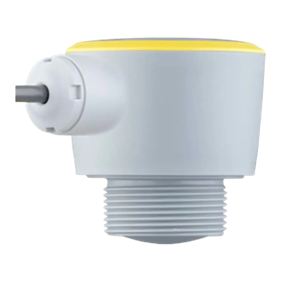
Hardware version from 1.0.0 • Software version from 1.2.0 Constituent parts Fig. 1: Components of VEGAPULS C 22 Radar antenna 2 Process fitting Electronics housing Cable outlet Type label The type label contains the most important data for identification and use of the instrument. VEGAPULS C 22 • Two-wire 4 … 20 mA/HART... -
Page 8: Principle Of Operation
Enter serial number manually in the VEGA Tools app (available free of charge in the respective stores) Principle of operation Application area VEGAPULS C 22 is a radar sensor for non-contact, continuous level measurement. It is suitable for liquids and solids in practically all industries. Functional principle The instrument emits a continuous, frequency-modulated radar signal through its antenna. The emitted signal is reflected by the medium... -
Page 9: Packaging, Transport And Storage
PC/notebook with DTM/PACTware Packaging, transport and storage Packaging Your instrument was protected by packaging during transport. Its capacity to handle normal loads during transport is assured by a test based on ISO 4180. VEGAPULS C 22 • Two-wire 4 … 20 mA/HART... -
Page 10: Accessories
Threaded adapters enable simple adaptation of devices with stand- ard threaded fittings, e.g. to process-side hygiene connections. Mounting accessories The mounting accessories are used for stable mounting of the device at the measuring point. The parts are available in various versions and sizes. VEGAPULS C 22 • Two-wire 4 … 20 mA/HART... -
Page 11: Mounting
Mounting bracket For the wall mounting, a mounting bracket with opening for thread G1½, e.g. from the VEGA product range, is recommended. The mounting of the device in the bracket is carried out via a G1½ counter nut of plastic. Take note of chapter " Mounting instructions" for the recommended distance to the wall. -
Page 12: Mounting Instructions
Fig. 8: Mounting of the radar sensor on round vessel tops In vessels with conical bottom it can be advantageous to mount the device in the centre of the vessel, as measurement is then possible down to the bottom. VEGAPULS C 22 • Two-wire 4 … 20 mA/HART... - Page 13 For nozzle mounting, the nozzle should be as short as possible and its end rounded. This reduces false reflections from the nozzle. With threaded socket, the antenna end should protrude at least 5 mm (0.2 in) out of the socket. VEGAPULS C 22 • Two-wire 4 … 20 mA/HART...
- Page 14 4 Mounting Fig. 12: Recommended threaded socket mounting of VEGAPULS C 22 If the reflective properties of the medium are good, you can mount VEGAPULS C 22 on sockets longer than the antenna. The socket end should be smooth and burr-free, if possible also rounded. Note: When mounting on longer nozzles, we recommend carrying out a false signal suppression (see chapter "...
-
Page 15: Measurement Setup - Flow
Measurement setup - Flow In general, the following must be observed while mounting the device: • Mounting the sensor on the upstream or inlet side VEGAPULS C 22 • Two-wire 4 … 20 mA/HART... - Page 16 The following examples serve as an overview for flow measurement. Rectangular overfall 3 ... 4 h 90° 90° Fig. 17: Flow measurement with rectangular flume: h = max. filling of the max. rectangular flume 1 Overfall orifice (side view) Upstream water Tailwater 4 Overfall orifice (view from tailwater) At smaller distances the measuring accuracy is reduced, see "Technical data". VEGAPULS C 22 • Two-wire 4 … 20 mA/HART...
- Page 17 4 Mounting Khafagi-Venturi flume 3 ... 4 x h 90° Fig. 18: Flow measurement with Khafagi-Venturi flume: h = max. filling of the max. flume; B = tightest constriction in the flume Position sensor 2 Venturi flume VEGAPULS C 22 • Two-wire 4 … 20 mA/HART...
-
Page 18: Connecting To Power Supply
Wire assignment, con- nection cable Fig. 19: Wire assignment in permanently connected connection cable Wire colour Function Polarity Brown Voltage supply, signal output Plus (+) Blue Voltage supply, signal output Minus (-) VEGAPULS C 22 • Two-wire 4 … 20 mA/HART... -
Page 19: Switch-On Phase
After connection to the power supply, the device carries out a self- test: • Internal check of the electronics • Output signal is set to failure The current measured value is then output on the signal cable. VEGAPULS C 22 • Two-wire 4 … 20 mA/HART... -
Page 20: Access Protection
If this document is lost, the emergency device code can be retrieved from your personal contact person after legitimation. The storage and transmission of the device codes is always encrypt- ed (SHA 256 algorithm). VEGAPULS C 22 • Two-wire 4 … 20 mA/HART... -
Page 21: Storing The Codes In Myvega
" PINs and Codes". This greatly simplifies the use of additional adjust- ment tools, as all Bluetooth access and device codes are automati- cally synchronized when connected to the " myVEGA" account VEGAPULS C 22 • Two-wire 4 … 20 mA/HART... -
Page 22: Setup With Smartphone/Tablet (Bluetooth)
Download the VEGA Tools app from the " Apple App Store", " Goog- le Play Store" or " Baidu Store" to your smartphone or tablet. Device activated Make sure that the VEGAPULS C 22 is activated, see chapter " Oper- ating modus, activate device". Connecting Connecting Start the adjustment app and select the function "... -
Page 23: Parameter Adjustment
Menu item display The selected menu item can be recognized by the colour change. Fig. 21: Example of an app view - Setup measured values Enter the requested parameters and confirm via the keyboard or the editing field. The settings are then active in the sensor. Close the app to terminate connection. VEGAPULS C 22 • Two-wire 4 … 20 mA/HART... -
Page 24: Setup With Pc/Notebook (Bluetooth)
After activating the integrated Bluetooth or the Bluetooth USB adapt- er, devices with Bluetooth are found and created in the project tree. Device activated Make sure that the VEGAPULS C 22 is activated, see chapter " Oper- ating modus, activate device". Connecting Select the requested device for the online parameter adjustment in Connecting the project tree. -
Page 25: Parameter Adjustment
(DTM) according to FDT standard are required. The latest PACTware version as well as all available DTMs are compiled in a DTM Collec- tion. The DTMs can also be integrated into other frame applications according to FDT standard. VEGAPULS C 22 • Two-wire 4 … 20 mA/HART... - Page 26 8 Setup with PC/notebook (Bluetooth) Fig. 23: Example of a DTM view - Setup, sensor adjustment VEGAPULS C 22 • Two-wire 4 … 20 mA/HART...
-
Page 27: Setup With Pc/Notebook (Vegaconnect)
149A, VEGAMET 381, VEGAMET 391. Common Ex separators are also usually equipped with a sufficient current limiting resistance. In such cases, the interface adapter can be connected parallel to the 4 … 20 mA cable (dashed line in the previous illustration). VEGAPULS C 22 • Two-wire 4 … 20 mA/HART... -
Page 28: Parameter Adjustment With Pactware
" DTM Collection/PACTware" attached to each DTM Collection and which can also be downloaded from the Internet. Detailed descrip- tions are available in the online help of PACTware and the DTMs. VEGAPULS C 22 • Two-wire 4 … 20 mA/HART... -
Page 29: Saving The Parameterisation Data
CD from the agency serving you. Saving the parameterisation data We recommend documenting or saving the parameterisation data via PACTware. That way the data are available for multiple use or service purposes. VEGAPULS C 22 • Two-wire 4 … 20 mA/HART... -
Page 30: Adjustment Menu
0 % correspond to 0 l Scaling unit 100 % correspond to 100 l Scaling format Display Menu language Displayed value Filling height Backlight Access protection Bluetooth access code Protection of the parameteri- Deactivated zation VEGAPULS C 22 • Two-wire 4 … 20 mA/HART... - Page 31 Pointer function distance, meas- urement reliability, meas. rate, electronic temperature Measured values Measured values Additional measured values Outputs Sensor information Device name, serial number, hardware/software version, de- vice revision, factory calibration date VEGAPULS C 22 • Two-wire 4 … 20 mA/HART...
-
Page 32: Description Of The Applications
• Further recommendations – False signal suppression with running agitator via adjustment app or PACTware/DTM Dosing vessel • Vessel: – Small vessels • Process/measurement conditions: – Frequent and fast filling/emptying – Tight installation situation VEGAPULS C 22 • Two-wire 4 … 20 mA/HART... - Page 33 Transportable plastic tank (IBC) • Process/measurement conditions: – Material and thickness different – Measurement through the vessel top, if appropriate to the application – Changed reflection conditions as well as jumps in measured values when changing vessels • Further recommendations VEGAPULS C 22 • Two-wire 4 … 20 mA/HART...
- Page 34 – Large distance to the medium – Steep angles of repose, unfavourable pouring positions due to outlet funnel and filling cone – Diffuse reflections due to structured vessel walls or internals – Multiple echoes/diffuse reflections due to unfavourable pouring positions with fine grain – Changing signal conditions when large amounts of material slip • Further recommendations VEGAPULS C 22 • Two-wire 4 … 20 mA/HART...
- Page 35 – Interfering reflections from fixtures or protective devices • Further recommendations – False signal suppression via adjustment app or PACTware/DTM Demonstration • Applications that are not typical level measurements – Instrument demonstration – Object recognition/monitoring – Measured value verification with higher measuring accuracy with reflection without bulk solids, e.g. via a measuring plate VEGAPULS C 22 • Two-wire 4 … 20 mA/HART...
-
Page 36: Diagnostics And Servicing
24 hour service hotline Should these measures not be successful, please call in urgent cases the VEGA service hotline under the phone no. +49 1805 858550. The hotline is also available outside normal working hours, seven days a week around the clock. -
Page 37: Diagnosis, Fault Messages
Function check - orange Maintenance required - blue Failure: Due to a malfunction in the instrument, a fault message is output. This status message is always active. It cannot be deactivated by the user. VEGAPULS C 22 • Two-wire 4 … 20 mA/HART... - Page 38 Repeat setup Byte 4, Bit 1 of Byte 0 … 5 Error in the instru- False signal suppression faulty Carry out a reset ment settings Error when carrying out a reset VEGAPULS C 22 • Two-wire 4 … 20 mA/HART...
- Page 39 Bit 5 of during operation Byte 14 … 24 No echo available Use a more suitable antenna/ Antenna dirty or defective sensor Remove possible false echoes Optimize sensor position and ori- entation VEGAPULS C 22 • Two-wire 4 … 20 mA/HART...
-
Page 40: Treatment Of Measurement Errors
If the output level is constant, the cause could also be the fault setting of the current output to " Hold value". If the level is too low, the reason could be a line resistance that is too high VEGAPULS C 22 • Two-wire 4 … 20 mA/HART... - Page 41 Measured value jumps to- Due to strong turbulence and foam gen- Carry out a false signal suppression wards 100 % during filling eration during filling, the amplitude of the level echo sinks. Measured value jumps to false signal time VEGAPULS C 22 • Two-wire 4 … 20 mA/HART...
- Page 42 Bulk solids: Measurement error at constant level Fault description Cause Rectification Measured value shows a too Min./max. adjustment not correct Adapt min./max. adjustment low or too high level Incorrect linearization curve Adapt linearization curve time VEGAPULS C 22 • Two-wire 4 … 20 mA/HART...
- Page 43 Minimize interfering installations in the close range by changing the polariza- tion direction time After eliminating the false signals, the false signal suppression must be de- leted. Carry out a new false signal suppression VEGAPULS C 22 • Two-wire 4 … 20 mA/HART...
-
Page 44: Software Update
Attach the completed form and, if need be, also a safety data sheet outside on the packaging • Ask the agency serving you to get the address for the return ship- ment. You can find the agency on our homepage. VEGAPULS C 22 • Two-wire 4 … 20 mA/HART... -
Page 45: Dismount
12.2 Disposal The device is made of recyclable materials. For this reason, it should be disposed of by a specialist recycling company. Observe the ap- plicable national regulations. VEGAPULS C 22 • Two-wire 4 … 20 mA/HART... -
Page 46: Certificates And Approvals
That is why we have introduced an environment management system with the goal of continuously improving company environmental pro- tection. The environment management system is certified according to DIN EN ISO 14001. Please help us fulfil this obligation by observ- ing the environmental instructions in chapters " Packaging, transport and Lagestoragerung", " Disposal" of these operating instructions. VEGAPULS C 22 • Two-wire 4 … 20 mA/HART... -
Page 47: Supplement
The antenna edge is also the reference plane for the measurement. Fig. 28: Data of the input variable Reference plane Measured variable, max. measuring range G type threaded connections only G type threaded connections only VEGAPULS C 22 • Two-wire 4 … 20 mA/HART... - Page 48 Ʋ Distance to installations > 200 mm (7.874 in) Ʋ Reflector Flat plate reflector Depending on application and medium With bulk solids Depending on the operating conditions Default values can be assigned individually. VEGAPULS C 22 • Two-wire 4 … 20 mA/HART...
- Page 49 Already included in the meas. deviation In case of deviations from reference conditions, the offset due to installation can be up to +/- 4 mm. This offset can be compensated by the adjustment. Determination of the temperature drift acc. to the limit point method With operating voltage U ≥ 24 V DC Time span after a sudden distance change from 1 m to 5 m until the output signal reaches 90 % of the final value for the first time (IEC 61298-2). Valid with operating voltage U ≥ 24 V DC. VEGAPULS C 22 • Two-wire 4 … 20 mA/HART...
- Page 50 IEC 60332-1-2, UL 1581 (Flametest VW-1) Bluetooth interface Bluetooth standard Bluetooth 5.0 (downward compatible to Bluetooth 4.0 LE) Frequency 2.402 … 2.480 GHz Max. emitted power +2.2 dBm Outside the specified beam angle, the energy level of the radar signal is 50% (-3 dB) less. EIRP: Equivalent Isotropic Radiated Power VEGAPULS C 22 • Two-wire 4 … 20 mA/HART...
- Page 51 IP66/IP68 (3 bar, 24 h) acc. to IEC 60529, Type 6P acc. to UL 50 Altitude above sea level 5000 m (16404 ft) Protection class Pollution degree Depending on the local conditions VEGAPULS C 22 • Two-wire 4 … 20 mA/HART...
-
Page 52: Dimensions
14 Supplement 14.2 Dimensions 64 mm (2.52") G1½ 1½ - 14 NPT R 1½ ø 58 mm (2.28") Fig. 30: Dimensions VEGAPULS C 22 Thread G1½ Thread 1½ NPT Thread R1½ VEGAPULS C 22 • Two-wire 4 … 20 mA/HART... -
Page 53: Industrial Property Rights
Les lignes de produits VEGA sont globalement protégées par des droits de propriété intellec- tuelle. Pour plus d'informations, on pourra se référer au site www.vega.com. VEGA lineas de productos están protegidas por los derechos en el campo de la propiedad indus- trial. Para mayor información revise la pagina web www.vega.com. - Page 54 Notes VEGAPULS C 22 • Two-wire 4 … 20 mA/HART...
- Page 55 Notes VEGAPULS C 22 • Two-wire 4 … 20 mA/HART...
- Page 56 Subject to change without prior notice © VEGA Grieshaber KG, Schiltach/Germany 2020 VEGA Grieshaber KG Phone +49 7836 50-0 Am Hohenstein 113...
Need help?
Do you have a question about the VEGAPULS C 22 and is the answer not in the manual?
Questions and answers