Sign In
Upload
Download
Table of Contents
Contents
Add to my manuals
Delete from my manuals
Share
URL of this page:
HTML Link:
Bookmark this page
Add
Manual will be automatically added to "My Manuals"
Print this page
×
Bookmark added
×
Added to my manuals
Manuals
Brands
FKI Manuals
Grill
GL 9000 Series
User manual
FKI GL 9000 Series User Manual
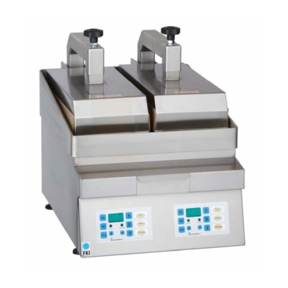
Turbomatic contact grill
Hide thumbs
1
2
Table Of Contents
3
4
5
6
7
8
9
10
11
12
13
14
15
16
17
18
19
20
21
22
23
24
25
26
27
28
29
30
31
page
of
31
Go
/
31
Contents
Table of Contents
Bookmarks
Table of Contents
Content of this Manual
Table of Contents
1 Introduction
2 Generally
Manufacturer
Machine Plate
Machine Plate Is Placed in the Back on the Left Side
3 Overview and Application
Generel Description
The Contact Grill Purpose and Intended Use
Warning on Foreseeable Misuse
Technical Specifications and Consumption
Placement of the Contact Grill
4 Safety and Residual Risks
Safety Precautions to be Taken by the User
Personal Safety Equipment
Residual Risks
5 Operation
Quick-Guide
Programming
Locking Display
Operating
Stop
Emergency Stop
Restart Efter Emergency Stop
Adjustment
Frying
6 Transport and Installation
Transport
Installation
Demands to the Installation Place
Connection
7 Maintenance, Fault-Finding and Repair
Cleaining and Order
Preventive Maintenannce
Fault Finding
Repair
Specifications on Spare Parts
8 End of Use
Destruction
9 Annex
Labels, Symbols and Pictograms
EC Declaration of Conformity
Wirering Diagrams
Advertisement
Quick Links
1
Programming
2
Quick-Guide
3
Adjustment
4
Fault Finding
5
Specifications on Spare Parts
Download this manual
Users Manual
Turbomatic contact grill
GL 9000 series
Version 2.4 – SEP 2016
Table of
Contents
Previous
Page
Next
Page
1
2
3
4
5
Advertisement
Table of Contents
Need help?
Do you have a question about the GL 9000 Series and is the answer not in the manual?
Ask a question
Questions and answers
Related Manuals for FKI GL 9000 Series
Grill FKI GL Series User And Service Manual
Sausage grill (12 pages)
Grill FKI GL Series Instructions For Use Manual
Sausage grill (17 pages)
Grill FKI GL 9640 User And Service Manual
Grill plate (12 pages)
Grill FKI GL 9001 User Manual
Turbomatic contact grill (31 pages)
Grill FKI GL 9002 User Manual
Turbomatic contact grill (31 pages)
Grill FKI GL 9003 User Manual
Turbomatic contact grill (31 pages)
Grill FKI GL 2002 Operating Instructions Manual
(25 pages)
Grill FKI GL 2002 User And Service Manual
Contact grill (16 pages)
Grill FKI GL-R Series Operating Instructions And Service Manual
Roller grill (26 pages)
Grill FKI GL-R Series Instructions For Use Manual
Fki roller grill (30 pages)
Grill FKI RG Series Instructions For Use Manual
Fki roller grill advanced (26 pages)
This manual is also suitable for:
Gl 9001
Gl 9002
Gl 9003
Gl 9010
Table of Contents
Print
Rename the bookmark
Delete bookmark?
Delete from my manuals?
Login
Sign In
OR
Sign in with Facebook
Sign in with Google
Upload manual
Upload from disk
Upload from URL


Need help?
Do you have a question about the GL 9000 Series and is the answer not in the manual?
Questions and answers