
Related Manuals for Eaton Cutler-Hammer NTV Series


Summary of Contents for Eaton Cutler-Hammer NTV Series
- Page 1 O&M Manual for Non-Automatic Transfer Switches (30 – 1200 Amperes) Instruction Bulletin New Information IB01602007E For more information visit: www.cutler-hammer.eaton.com...
-
Page 2: Table Of Contents
7.2 Procedures..........25 For more information visit: www.cutler-hammer.eaton.com... - Page 3 Periodic Maintenance Procedures ............. . . 25 IB01602007E For more information visit: www.cutler-hammer.eaton.com...
-
Page 4: Section 1: Introduction
Once normal power purchaser regarding a particular installation, application is restored, the load is automatically or manually transferred or maintenance activity, an Eaton/Cutler-Hammer represen- back to the normal power source, again depending upon the tative should be contacted. -
Page 5: Design Configuration
Example: Catalog Number (circled numbers correspond to position headings in Table 1 ) Figure 4. Vertical Design Automatic Transfer Switch Equipment Shown with Deadfront Cover Removed (225 – 1200 Amperes) NT V E KD A 3 0300 X S U IB01602007E For more information visit: www.cutler-hammer.eaton.com... - Page 6 Vertical orientation (225 – 1200 amperes). Horizontal orientation (30 – 150 amperes). Contact factory for availability. 1200 amperes not UL or CSA listed. Units with a “Switching Device Arrangement” other than “A” will not include a CSA listing. For more information visit: www.cutler-hammer.eaton.com IB01602007E...
-
Page 7: Environmental Conditions
95% humidity (non-condensing). The ambient temperature range for operation is between -20 and +70°C. Figure 5. Horizontal Design Automatic Transfer Switch Equipment (30 – 100 Amperes) IB01602007E For more information visit: www.cutler-hammer.eaton.com... -
Page 8: Section 2: Receiving, Handling And Storage
Important documents, such as test reports, wiring diagrams, appropriate instruction leaflets and a warranty registration card, are enclosed within the bag and should be filed in a safe place. For more information visit: www.cutler-hammer.eaton.com IB01602007E... -
Page 9: Section 3: Equipment Description
(Figures 6 possibilities, it is the only specific type that will be and 7). discussed in this section. Figure 7. Typical Horizontal Design Power Panel (Mounted) Figure 6. Typical Vertical Design Power Panel (Unmounted) IB01602007E For more information visit: www.cutler-hammer.eaton.com... -
Page 10: Vertical Design Steel Base Plate
Figure 8. Molded Case Switches Mounted in Vertical Design ing access to other parts of the power panel (Figure 3). (Transfer Mechanism Removed for Clarity) For more information visit: www.cutler-hammer.eaton.com IB01602007E... -
Page 11: Voltage Selection Panel
It also provides indication of source avail- ability, switch position and trip indication (if applicable). Figure 9. Vertical Design Voltage Selection Panel with Voltage Being Selected Figure 10. Typical Logic Panel (Door Mounted) IB01602007E For more information visit: www.cutler-hammer.eaton.com... -
Page 12: Options
Provides transfer switch with seismic capability exceeding the worst case Zone 4 required levels per both the Uniform 7.50 Building Code and the California Building Code. (190.5) Figure 11. Charger Mounting Dimensions in Inches (mm) For more information visit: www.cutler-hammer.eaton.com IB01602007E... -
Page 13: Enclosure
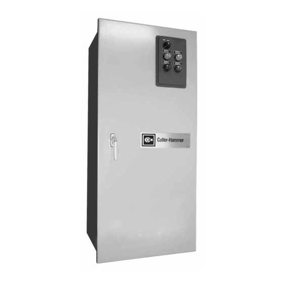
UL 489 and UL 1087. The frequency of such a re-submittal can be as often as every quarter for a low ampere device. Figure 12. Typical NEMA Type 1 Enclosure (Door Closed) IB01602007E For more information visit: www.cutler-hammer.eaton.com... -
Page 14: Section 4: Installation And Wiring
EXTREME CARE SHOULD BE TAKEN TO PROTECT THE TRANSFER SWITCH FROM DRILL CHIPS, FILINGS AND OTHER CONTAMINANTS WHEN MAKING THE CABLE ENTRY HOLES AND MOUNTING THE ENCLOSURE TO PREVENT COMPONENT DAMAGE OR A FUTURE MALFUNCTION. For more information visit: www.cutler-hammer.eaton.com IB01602007E... -
Page 15: Vertical Design Power Panel Mounting Reference In Inches (Mm)
Step 3: Gently lift the enclosure and guide the elongated holes in the upper mounting flange over the upper mounting bolts, but do not completely tighten the bolts. IB01602007E For more information visit: www.cutler-hammer.eaton.com... -
Page 16: Vertical Design Load Lug Location
Note: There are grooves in the back of the power panel and in the mounting bracket that keep the polyester phase barriers in their proper positions. Figure 14. Vertical Design Load Lug Assembly Shown Mounted For more information visit: www.cutler-hammer.eaton.com IB01602007E... -
Page 17: Typical (225 - 1200 Amperes) Vertical Design Transfer Switch Equipment (Door Open And Deadfront Shield Removed)
Type LD 25 (33.8) properly in the grooves provided. When making Type MA/MD 25 (33.8) any bolted connection to the bus, comply with Type ND/NB 25 (33.8) the torque requirements as outlined in Table 3. IB01602007E For more information visit: www.cutler-hammer.eaton.com... -
Page 18: Typical (30 - 100 Amperes) Horizontal Design Transfer Switch Equipment (Door Open)
Step 12: Reconnect the connector plugs and the will line up the four correct mounting holes in transfer switch equipment is now configured for the power panel with the pre-tapped inserts bottom entry. in the rear of the enclosure. For more information visit: www.cutler-hammer.eaton.com IB01602007E... -
Page 19: Power Cable Connections
Prepare the stripped conductor termination end by cleaning it with a wire brush. If aluminum conductors are used, apply an appropriate joint compound to the clean conductor surface area. Refer to Figure 14 for approximate locations of power connections. IB01602007E For more information visit: www.cutler-hammer.eaton.com... -
Page 20: Wiring
Horizontal design transfer switches are furnished with an adjustable line voltage plug and receptacles below the power panel. To change the line voltage, remove the covers and insert the plug in the desired receptacle (Figure 17). For more information visit: www.cutler-hammer.eaton.com IB01602007E... -
Page 21: Section 5: Operation
This feature ensures no operator problems should the switch automatically operate while the manual handle is being used. Figure 19. Indicator Wheel Shown Mounted in Mechanism with Motor Mounted Under Wheel IB01602007E For more information visit: www.cutler-hammer.eaton.com... -
Page 22: Horizontal Design Operation
This is accomplished by unplugging the disconnect link. Any attempt to operate the manual handle without first isolating the motor circuit causes an automatic transfer to the source indicated by the source selector switch. Figure 21. Motor Disconnect Being Unplugged For more information visit: www.cutler-hammer.eaton.com IB01602007E... -
Page 23: Non-Automatic Operation (Electrically Operated)
Source 1 to Source 2 or vice versa. Figure 22. Electrical Operation Pushbutton and Position Indicating Lights Shown Mounted IB01602007E For more information visit: www.cutler-hammer.eaton.com... -
Page 24: Section 6: Testing And Problem Solving
ATED EQUIPMENT SHOULD BE PERMITTED TO PERFORM THE PROBLEM SOLVING FUNCTION. IF AN INDIVIDUAL DOES NOT FEEL QUALIFIED TO PERFORM THE PROBLEM SOLVING FUNCTION, THE INDIVIDUAL SHOULD NOT ATTEMPT TO PERFORM ANY OF THESE PROCEDURES. For more information visit: www.cutler-hammer.eaton.com IB01602007E... -
Page 25: Section 7: Maintenance
Always be alert for an accumulation of dirt in and around the structure, loose parts and/or hardware, cracks and/or discoloration to insula- tion, and damaged or discolored components. IB01602007E For more information visit: www.cutler-hammer.eaton.com... - Page 26 Quincy, Mass. NEMA is the registered trademark and service mark of the National Electrical Manufacturers Association. Uniform Building Code (UBC) is a trademark of the International Conference of Building Officials (ICBO). UL is a federally registered trademark of Underwriters Laboratories Inc. For more information visit: www.cutler-hammer.eaton.com IB01602007E...
- Page 27 O&M Manual for Instruction Bulletin Non-Automatic Transfer Effective: June 2003 Page 27 Switches (30 – 1200 Amperes) This page intentionally left blank. IB01602007E For more information visit: www.cutler-hammer.eaton.com...
- Page 28 Page 28 Effective: June 2003 Switches (30 – 1200 Amperes) Eaton Corporation Cutler-Hammer business unit 1000 Cherrington Parkway Moon Township, PA 15108-4312 tel: 1-800-525-2000 www.cutler-hammer.eaton.com © 2003 Eaton Corporation All Rights Reserved Printed in USA Publication No. IB01602007E June 2003...
Need help?
Do you have a question about the Cutler-Hammer NTV Series and is the answer not in the manual?
Questions and answers