Advertisement
Instruction Booklet IB.31F.01.T.K
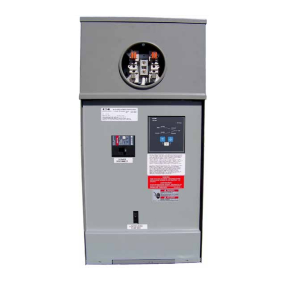
O & M Manual for the EGS Metered, Service
Entrance Automatic Transfer Switch with ATC-100 Control
Effective January 2012
Contents
Description
1. Introduction . . . . . . . . . . . . . . . . . . . . . . . . . . . . 2
2. Receiving, Handling, and Storage . . . . . . . . . . . 5
3. Equipment Description . . . . . . . . . . . . . . . . . . . 5
4. Installation and Wiring . . . . . . . . . . . . . . . . . . . . 8
5. Functional Testing . . . . . . . . . . . . . . . . . . . . . . 12
6. Adjustments . . . . . . . . . . . . . . . . . . . . . . . . . . 13
Page
Advertisement

Related Manuals for Eaton EGS Series


Summary of Contents for Eaton EGS Series
-
Page 1: Table Of Contents
Instruction Booklet IB.31F.01.T.K Effective January 2012 O & M Manual for the EGS Metered, Service Entrance Automatic Transfer Switch with ATC-100 Control Contents Description Page 1. Introduction ......2 2. -
Page 2: Introduction
In no EQUiPMEnT raTingS LaBEL iS SHOWn in FigUrE 1. event will Eaton be responsible to the purchaser or user in contract, in tort (including negligence), strict liability, or otherwise for any spe- cial, indirect, incidental or consequential damage, or loss whatsoev-... - Page 3 Canadian approved service entrance rated disconnect source, the ATS transfers the load to the generator power source. means. The ATS is controlled by an Eaton ATC-100 controller and Once the utility power is restored, the load is automatically trans- ferred back to the utility power source (Figure 2).
- Page 4 Transfer Transfer is defined as a change of the load connection from the Utility to the Generator power source. Unconnected Unconnected is defined as when the input is not shorted by an external contact or connection. Eaton Corporation www.eatoncanada.ca...
-
Page 5: Receiving, Handling, And Storage
Storage 3.1 Introduction 2.1 Receiving The Eaton metered, service entrance rated ATS is assembled and tested at the factory. It is designed to be used in conjunction with Every effort is made to ensure that the ATS equipment arrives at standby power distribution equipment to provide an alternate source its destination undamaged and ready for installation. - Page 6 Dropout: 80% of nominal Pickup: 90% of nominal 3.4 EGS ATS Features Underfrequency: A variety of standard and optional features are available for Eaton Dropout: 90% of nominal ATSs. all features or combinations of features may not be available Pickup: 95% of nominal on specific aTSs.
- Page 7 If the Utility power supply fails, then the ATC 100 will begin the sequence of operations necessary to transfer the load circuit to the Generator power supply. All Feature 26 monitoring and protection functions are Failsafe operations. Eaton Corporation www.eatoncanada.ca...
-
Page 8: Installation And Wiring
In the case of an overhead service entrance installation the wire- ways may be removed to provide additional working space in the for application by UL. In addition, Eaton ATSs are listed in File enclosure. Once removed the supplied blanking plates must be E313744 by Underwriters Laboratories, Inc. - Page 9 Also verify that the cables comply with all local electrical codes. Standard ATS Figure 9. Power and Neutral Utility Cable Connection Locations. equipment, as supplied from the factory, will accommodate the wire sizes shown in Table 2. Eaton Corporation www.eatoncanada.ca...
- Page 10 The generator and load ground cable to the generator and load • ground lugs on the ground bar assembly. Warning FaiLUrE TO PrOPErLY COnnECT THiS TranSFEr SWiTCH PEr nFPa 70, THE naTiOnaL ELECTriC CODE, MaY rESULT in PrODUCT FaiLUrE, FirE, LOSS OF PrOPErTY, LOSS OF LiFE, ETC. Eaton Corporation www.eatoncanada.ca...
- Page 11 Prior to making the generator start connection to the aTS, set the generator control selector switch to the OFF position to prevent an unwanted generator start. Control wiring, such as the generator start wires, must be run in a separate conduit from the power cables. Eaton Corporation www.eatoncanada.ca...
-
Page 12: Functional Testing
Step 2 of Section 5.2. Position the generator control selector switch, located on the standby generator, to the AUTOSTART position. (It may also be labeled REMOTE START or AUTO.). Close the generator power source circuit breaker opened in Step 2 of Section 5.2. Eaton Corporation www.eatoncanada.ca... -
Page 13: Adjustments
Step 6: Move the lever up to go to utility or move the lever down to go to generator. Step 7: Reconnect the power. Step 8: If automatic operation is required, disconnect all sources of power, reinstall the J7 connector, and reconnect the power. Figure 14. ATS Manual Operating Lever. Eaton Corporation www.eatoncanada.ca... -
Page 14: Maintenance And Component Replacement
If a switching device is used for frequent switching during normal operation, this step can be disre- the wiping action by the contacts. garded. g. Return the transfer switch equipment to service. Make certain all barriers are in place and the door is closed. Re-apply generator and utility power. Eaton Corporation www.eatoncanada.ca... - Page 15 Source 2 Sensing Input Circuit Breaker Load Connections S1 Coil Genrator Utility Start Signal Contactor Coil Terminal Blocks Source 2 Generator S2 Coil Generator Contactor Coil Figure 16. Wiring Diagram for the EGS ATS (Shown Connected to Source 2). Eaton Corporation www.eatoncanada.ca...
- Page 16 Instruction Booklet IB.31F.01.T.K O & M Manual for the EGS Metered, Service Entrance Automatic Transfer Switch with ATC-100 Control Effective January 2012 7.3 Maintenance Log Date action Example: 01/01/12 Inspected and cleaned. Eaton Corporation www.eatoncanada.ca...
- Page 17 HaS BEEn rEPLaCED. TEST THE SYSTEM FOr PrOPEr FUnCTiOn- aLiTY. 7.5 Troubleshooting Table 6 contains troubleshooting information for the EGS ATS. If a problem still exists after completing the troubleshooting procedures, contact an authorized Eaton sales representative. Table 6. Troubleshooting Chart. Problem Cause Correction The automatic transfer switch does not transfer to the generator.
- Page 18 4.69” (119mm) 2.36” (3) 1”, 1¼”, 1½”, 2”, 2½” (60mm) (1) ¾”, 1” 7.25” (2) ½”, 1” (184mm) (1) ½” Concentric Knockouts 18.04” (458mm) Figure 17. Dimensions and Plan View of a Service Entrance EGS (in.) (200A). Eaton Corporation www.eatoncanada.ca...
- Page 19 Instruction Booklet IB.31F.01.T.K O & M Manual for the EGS Metered, Service Entrance Automatic Transfer Switch with ATC-100 Control Effective January 2012 Notes: Eaton Corporation www.eatoncanada.ca...
- Page 20 The sole source governing the rights and remedies of any purchaser of this equipment is the contract between the purchaser and Eaton. nO WarranTiES, EXPrESSED Or iMPLiED, inCLUDing WarranTiES...
Need help?
Do you have a question about the EGS Series and is the answer not in the manual?
Questions and answers