Advertisement
Instructi o n Bookl e t IB0162064EN
O & M Manual for the EGS Service
Entrance Automatic Transfer Switch
Effecti v e January 2014
Contents
Description
1. Introduction . . . . . . . . . . . . . . . . . . . . . . . . . . . . 2
2. Receiving, Handling, and Storage . . . . . . . . . . . 5
3. Equipment Description . . . . . . . . . . . . . . . . . . . 5
4. Installation and Wiring . . . . . . . . . . . . . . . . . . . . 8
5. Functional Testing . . . . . . . . . . . . . . . . . . . . . . 12
6. Adjustments . . . . . . . . . . . . . . . . . . . . . . . . . . 13
Page
Advertisement

Related Manuals for Eaton EGS Series


Summary of Contents for Eaton EGS Series
-
Page 1: Table Of Contents
Instructi o n Bookl e t IB0162064EN Effecti v e January 2014 O & M Manual for the EGS Service Entrance Automatic Transfer Switch Contents Description Page 1. Introduction ......2 2. -
Page 2: Introduction
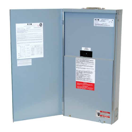
In no EQUiPMEnT raTingS LaBEL iS SHOWn in FigUrE 1. event will Eaton be responsible to the purchaser or user in contract, in tort (including negligence), strict liability, or otherwise for any spe- cial, indirect, incidental or consequential damage, or loss whatsoev- Figure 1. - Page 3 The ATS is controlled by source, the ATS transfers the load to the generator power source. an Eaton RTC-100 controller or relay, and utilizes power contactors Once the utility power is restored, the load is automatically trans- ferred back to the utility power source (Figure 2).
- Page 4 Transfer is defined as a change of the load connection from the Utility to the Generator power source. Unconnected Unconnected is defined as when the input is not shorted by an external contact or connection. Eaton Corporati o n www.eatoncanada.ca...
-
Page 5: Receiving, Handling, And Storage
Record any external and internal damage for reporting to the transportation carrier and to the Eaton sales representative, once a thorough inspection is complete. All claims should be as specific as possible and include the Shop Order and General Order numbers. -
Page 6: Equipment Description
Effecti v e January 2014 Section 3: Equipment Description 3.1 Introduction The Eaton metered, service entrance rated ATS is assembled and tested at the factory. It is designed to be used in conjunction with standby power distribution equipment to provide an alternate source of power to critical circuits in the event that the primary power source is interrupted. - Page 7 23, 194: Transfer signal connection from generator Install T1 Fuse Block (provided with gen- erator) in this position, install jumper to L1 or L2 to ensure generator battery is charging when on utility and on generator source Eaton Corporati o n www.eatoncanada.ca...
- Page 8 Warning FaiLUrE TO PrOPErLY COnnECT THiS TranSFEr SWiTCH PEr nFPa 70, THE naTiOnaL ELECTriC CODE, MaY rESULT in PrODUCT FaiLUrE, FirE, LOSS OF PrOPErTY, LOSS OF LiFE, ETC. Eaton Corporati o n www.eatoncanada.ca...
-
Page 9: Functional Testing
Step 2 of Section 5.2. Position the generator control selector switch, located on the standby generator, to the AUTOSTART position. (It may also be labeled REMOTE START or AUTO.). Close the generator power source circuit breaker opened in Step 2 of Section 5.2. Eaton Corporati o n www.eatoncanada.ca... - Page 10 Step 7: The ATS Time Delay Emergency (Generator) to Normal (Utility) (TDEN) timer will begin timing, and the solenoid will engage and automatically switch from the GENERATOR to the UTILITY position and the generator will shut down after a cool down period. Eaton Corporati o n www.eatoncanada.ca...
-
Page 11: Adjustments
Reconnect the power. Step 8: If automatic operation is required, disconnect all sources of power, reinstall the J7 connector, and reconnect the power. Figure 9. ATS Manual Operating Lever. Figure 10. ATS Manual Operating Handle. Eaton Corporati o n www.eatoncanada.ca... -
Page 12: Maintenance And Component Replacement
If a switching device is used for frequent switching during normal operation, this step can be disre- the wiping action by the contacts. garded. g. Return the transfer switch equipment to service. Make certain all barriers are in place and the door is closed. Re-apply generator and utility power. Eaton Corporati o n www.eatoncanada.ca... - Page 13 O & M Manual for the EGS Servi c e Entrance Automati c Transfer Swi t ch Effecti v e January 2014 Figure 11. Wiring Diagram for the EGS ATS (Shown Connected to Normal Source 1- (N) Utility). Eaton Corporati o n www.eatoncanada.ca...
- Page 14 Instruction Booklet IB0162064EN O & M Manual for the EGS Servi c e Entrance Automati c Transfer Swi t ch Effecti v e January 2014 7.3 Maintenance Log Date action Example: 01/01/12 Inspected and cleaned. Eaton Corporati o n www.eatoncanada.ca...
- Page 15 HaS BEEn rEPLaCED. TEST THE SYSTEM FOr PrOPEr FUnCTiOn- aLiTY. 7.5 Troubleshooting Table 6 contains troubleshooting information for the EGS ATS. If a problem still exists after completing the troubleshooting procedures, contact an authorized Eaton sales representative. Table 6. Troubleshooting Chart. Problem Cause Correction The automatic transfer switch does not transfer to the generator.
- Page 16 O & M Manual for the EGS Servi c e Entrance Automati c Transfer Swi t ch Effecti v e January 2014 Figure 12. Dimensions and Plan View of a Service Entrance EGS (in.) (200A). Eaton Corporati o n www.eatoncanada.ca...
- Page 17 Instruction Booklet IB0162064EN O & M Manual for the EGS Servi c e Entrance Automati c Transfer Swi t ch Effecti v e January 2014 Notes: Eaton Corporati o n www.eatoncanada.ca...
- Page 18 The sole source governing the rights and remedies of any purchaser of this equipment is the contract between the purchaser and Eaton. nO WarranTiES, EXPrESSED Or iMPLiED, inCLUDing WarranTiES...
Need help?
Do you have a question about the EGS Series and is the answer not in the manual?
Questions and answers