Table of Contents
Advertisement
Advertisement
Table of Contents

Related Manuals for E Instruments E8500 Plus


Summary of Contents for E Instruments E8500 Plus
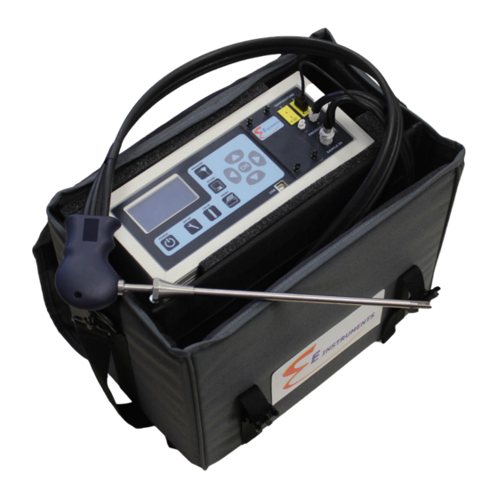
- Page 1 INSTRUCTION & OPERATIONS MANUAL E8500 Plus PORTABLE INDUSTRIAL INTEGRATED EMISSIONS SYSTEM COMBUSTION GAS ANALYZER E Instruments International LLC 402 Middletown Blvd, Suite 216 Langhorne, PA, USA 19047 Phone (215) 750-1212 Fax (215) 750-1399 www.E-Inst.com...
-
Page 2: Table Of Contents
E8500 Instruction & Operations Manual version 1.017 TABLE OF CONTENTS LIST OF ABBREVIATIONS ..................... 3 ANALYZER OPTIONS ....................4 CHAPTER 1 FUNDAMENTALS ......................5 CHAPTER 2 THE INSTRUMENT KEYBOARD .................. 11 CHAPTER 3 BASIC INSTRUMENT OPERATION ................12 CHAPTER 4 POWER REQUIREMENTS ................... -
Page 3: List Of Abbreviations
E8500 Instruction & Operations Manual version 1.017 LIST OF ABBREVIATIONS PARAMETERS Excess air Carbon monoxide (a toxic gas) Carbon dioxide – NDIR measurement OR calculated from O Draft/Pressure DUTY Duty cycle is a power setting given in percent Combustion efficiency (for boilers and furnaces, does not apply to engines) Hydrocarbons (NDIR) measurement –... -
Page 4: Analyzer Options
1.017 ANALYZER OPTIONS The E INSTRUMENTS Model 8500 Plus is an extremely versatile emissions measurement system that meets practically all emissions requirements. It has been designed as a modular system, permitting the installation, in the field, of most of the various available options. -
Page 5: Chapter 1 Fundamentals
1.017 CHAPTER 1 FUNDAMENTALS The E INSTRUMENTS Model E8500 Plus Integrated Emissions System is a portable state of the art analyzer designed to measure, record and remotely transmit combustion parameters used for the following tasks: A. To measure the oxide of nitrogen emissions from stationary combustion sources by means of electrochemical sensors in accordance with the EPA Provisional Reference Method (EMTIC CTM-022, CTM-030, &... - Page 6 UNPACKING THE INSTRUMENT Every E INSTRUMENTS Model E8500 Plus includes as standard equipment: • Emissions Analyzer Model E8500 Plus with integrated chiller conditioning system and automatic condensate drain •...
- Page 7 5. The instrument can have up to six electrochemical gas sensors, one PID sensor, and three infrared (NDIR) gas sensors. The E8500 Plus has three temperature sensors total. 6. All sensor readings are single range readings with ranges listed in Appendix A.
- Page 8 It is best to let the E8500 Plus run with the main gas pump on for at least a few minutes after measuring is done to let all of the condensate automatically drain out of the analyzer and to also fully purge the stack gases out of the unit.
- Page 9 E8500 Instruction & Operations Manual version 1.017 AUTOZERO ERRORS & BASIC TROUBLESHOOTING AUTOZERO ERRORS Channel Possible Causes Resolution Sensor has been Purge for 10 minutes, (Electrochemical recently exposed to monitor sensor voltage, sensors) gas and has not yet and re-zero. returned to zero.
- Page 10 E8500 Instruction & Operations Manual version 1.017 TROUBLESHOOTING Symptoms Possible Causes Resolution Battery is dead. Plug in the charger. Analyzer will not turn Analyzer should turn on. on. (Screen is off) Battery is not Check the charger and charging. jack. Check the case for excessive heat.
-
Page 11: The Instrument Keyboard
E8500 Instruction & Operations Manual version 1.017 CHAPTER 2 THE INSTRUMENT KEYBOARD A brief explanation of the instrument’s buttons is as follows: CALIB Controls calibration settings and zeroing of the analyzer’s sensors. SETUP Controls all customization parameters (such as measurement units) for the analyzer MEASURE Displays the analyzer’s currently measured data in either of two fonts:... -
Page 12: Basic Instrument Operation
PC board To operate the instrument, follow the steps outlined below. 1. Turn the E8500 Plus analyzer on. The instrument pump will immediately turn on and the E INSTRUMENTS logo will appear. Press OK to run the autozero cycle. - Page 13 (reverse color) will point to: Print Test Record Press the OK key to execute a printout on the E8500 Plus’s remote printer. 9. Measured data can be stored in the analyzer’s internal memory. Please refer to Chapter 8 for more details about data storage.
-
Page 14: Chapter 4 Power Requirements
A new E8500 Plus should be charged with the unit powered off for 12 to 24 hours. It is not suggested to charge the unit for more than 24 hours when powered off. -
Page 15: Chapter 5 - Technical
E8500 Instruction & Operations Manual version 1.017 CHAPTER 5 - TECHNICAL SAMPLE FLOW & SAMPLE CONDITIONING SYSTEM PART A. THE EXTRACTION PROBE AND SAMPLING LINE A number of different types of probes are available depending on the application requirements. The probe consists of the extraction probe, the sampling line and the stack thermocouple. - Page 16 E8500 Instruction & Operations Manual version 1.017 and SO are gases that are highly soluble in water. To prevent significant loss of and SO during transport of the sample from the probe to the analyzer, the following conditions must be satisfied: 1.
- Page 17 E8500 Instruction & Operations Manual version 1.017 The sample conditioning system located inside the analyzer as shown in the following photo: Damper Line Filter Sampling Pump Thermocouple Connectors Condensate Condensate Water Trap Pump Thermo-Electric Chiller with Fan The following components are mounted on the conditioning system: 1.
- Page 18 E8500 Instruction & Operations Manual version 1.017 3. Condensate pump. This peristaltic pump operates automatically on a periodic basis that can be set by the customer to remove the condensed water from the water trap and discharge it in the back of the instrument. The default operation is 30 seconds on, 25 minutes off.
-
Page 19: Chapter 6 - Technical Sensors
E8500 Instruction & Operations Manual version 1.017 CHAPTER 6 - TECHNICAL SENSORS The great versatility of the Model 8500 Plus Emissions system is partly due to the large number of sensors available within a single analyzer. These sensors are primarily gas sensors and can be grouped into three categories based on their principle of operation: 1. - Page 20 E8500 Instruction & Operations Manual version 1.017 1. ELECTROCHEMICAL SENSORS All electrochemical sensors, except for the H S sensor are of the 5 series type mounted on bayonet style fittings for easy removal. The electrochemical sensors are described below following the order by which the gas flows through the manifold.
- Page 21 E8500 Instruction & Operations Manual version 1.017 Unlike the other toxic sensors the carbon monoxide sensor is mounted in an assembly that includes a three way electronic valve and an additional oxygen (dilution) sensor. The sensor itself has an inboard filter to remove interference from NO gas. This sensor has four electrodes.
- Page 22 10.6 eV or lower. The only other gases measured by the E8500 Plus and are typically found in a combustion flue/exhaust gas that have an ionization potential less than 10.6 eV and can affect the measurement of the VOC sensor are NO (9.25 eV) and H2S (10.46 eV).
- Page 23 E8500 Instruction & Operations Manual version 1.017 sensors and also monitors the temperature of the cells as required by the EPA’s Method CTM-034. B. Stack temperature sensor The thermocouple is located at the tip of the probe. It measures the stack temperature minus the ambient temperature.
-
Page 24: Chapter 7 Analyzer Setup
E8500 Instruction & Operations Manual version 1.017 CHAPTER 7 ANALYZER SETUP The SETUP MENU allows the operator to change system parameters. 1 ‘15 12:45:00 Fuel: NATURAL GAS Temperature Units: F Measure Units: Pressure Units: inWC O2 Reference: TRUE Pumps: AUTO 1500cc/m Dilution Duty: Water Drain: 25min... - Page 25 E8500 Instruction & Operations Manual version 1.017 A more detailed explanation of each parameter follows: 1) DATE & TIME: The analyzer’s internal clock is displayed in the format month-day- year, hour-minute-second. Hours are always displayed using a 24-hour clock format. 2) FUEL: The analyzer has the following fifteen fuels stored in its memory (1) #2 OIL (2) #4 OIL...
- Page 26 E8500 Instruction & Operations Manual version 1.017 value is 0.25. If the thermal efficiency is not known, it may be computed by using the engine's BSFC (brake-specific fuel consumption-BTU/BHP-HR) as follows: ENGINE EFFICIENCY = 2547/BSFC NOTE: Emission measurements in PPM, MGM, #/B and GBH are carried out on a dry basis as required by the EPA’s 40CFR75 .
- Page 27 E8500 Instruction & Operations Manual version 1.017 NOTE: Setting the OXYGEN REFERENCE to a value other than TRUE affects values of emissions concentrations in PPM and MGM. It does not affect values in #/B or GBH. 8) PUMP: Pump status is displayed: a) AUTO - Automatic sample and dilution control mode is selected, and typical flow- rate is shown.
- Page 28 E8500 Instruction & Operations Manual version 1.017 17) VELOCITY UNITS: (Velocity Option) Select between feet per second (FPS), meters per second (MPS), cubic feet per minute (CFM), or cubic meter per minute (CMM). VELOCITY AND DRAFT/PRESSURE CAN NOT BE MEASURED SIMULTANEOUSLY.
-
Page 29: Internal Data Storage
Name Buffers Erase Buffers The E8500 Plus has 2000 internal storage tags. Each tag stores one complete set of emissions data. There are two ways to store emissions data to the analyzer’s buffer. You can either store data by selecting the option STORE CURRENT DATA after pressing the STORE key, or alternatively you can make use of the analyzer’s capability... - Page 30 E8500 Instruction & Operations Manual version 1.017 4. START PERIODIC STORE: This will turn on the periodic store function. In this mode, the unit will continuously store data at an interval displayed on the next line. Once enabled, this line will read: STOP PERIODIC. At the end of the test interval, the screen will automatically switch to the Name Buffers screen, prompting the user to enter a unique name for the sequence.
-
Page 31: Wireless Remote Printer
The E8500 Plus uses a wireless remote printer. The printer is powered by a rechargeable battery. The battery can be charged with the same charger that is used for the E8500 Plus analyzer. The printer is optional with the E8500 Plus. - Page 32 E8500 Instruction & Operations Manual version 1.017 LOG INTERVAL: This selects the interval between each log entry. The interval can be set between 1 and 60 seconds. PRINT BUFFER: This option is used to print data stored in the analyzer’s memory. Each line corresponds to one storage tag.
-
Page 33: Chapter 10 Calibration
E8500 Instruction & Operations Manual version 1.017 CHAPTER 10 CALIBRATION Every instrument must occasionally be calibrated against some known value of a parameter in order to make sure that its accuracy has not deteriorated. Instrument calibration requires two steps. The first step is to zero the analyzer in a clean, ambient temperature environment. - Page 34 SENSORS. Make sure that the analyzer pump is pulling in air. At the end of the autozero period the E8500 Plus reads the output of all gas sensors and sets them all to zero, with the exception of the oxygen that it sets to 20.9%.
- Page 35 You must not feed gas to the E8500 Plus under pressure and you must not starve the E8500 Plus's pump for gas. When feeding the gas, you must maintain a reasonably constant pressure, near ambient pressure.
- Page 36 E8500 Instruction & Operations Manual version 1.017 Gas Sensor Calibration Procedure The following page illustrates the sequence of key strokes to carry out a span calibration of the analyzer. It is assumed that the instrument has been auto-zeroed and there have been no error messages. Electrochemical Gas Sensors 1.
- Page 37 E8500 Instruction & Operations Manual version 1.017 7. Turn on the gas flow and observe gas readings. If the gas reading for the sensor being calibrated does not increase after a few seconds, turn off the gas flow until the problem is found. Otherwise, press OK. 8.
- Page 38 E8500 Instruction & Operations Manual version 1.017 Stack Draft & Pressure Calibration Procedure Connect a pressure calibration standard to the pressure (+) connector on the front of the instrument. In the SETUP menu, make sure the velocity sensor is off. Press the “CALIB”...
-
Page 39: Chapter 11 Communications
E8500 Instruction & Operations Manual version 1.017 CHAPTER 11 COMMUNICATIONS The E8500 Plus analyzer communicates wirelessly with a computer using its internal Bluetooth module. The communication protocol is as follows: BAUD RATE: 115000 baud FORMAT: 8 bits, 1 stop bit, no parity... -
Page 40: Chapter 12 Maintenance
1.017 CHAPTER 12 MAINTENANCE The E8500 Plus emissions analyzer is a sophisticated analytical instrument designed to perform accurate emissions measurements. However, because the analyzer is a portable, field use instrument that can be used in many environments, care must be taken to prevent physical and environmental abuse to help maintain trouble-free operation. - Page 41 When replacing the condensation disk filter, make sure that the filter’s lettering is facing the front/top of the analyzer. One of the E8500 Plus options is a sintered pre-filter that threads into the of the 40”(1m) and 60”(1.5m) probes. If the sintered filter option is included, this item should be periodically inspected and cleaned as needed.
- Page 42 E8500 Instruction & Operations Manual version 1.017 B. Condensation removal Some water vapor in the stack gas may condense inside the extraction probe and sampling line. However, any remaining excess water vapor in the sample gas will condense inside the thermoelectrically operated chiller, which is located inside the analyzer right behind the Sample In connection.
- Page 43 E8500 Instruction & Operations Manual version 1.017 SENSOR 30 minutes S SENSOR 30 minutes VOC SENSOR 30 minutes Span calibrate the sensor as explained in Chapter 10. If you are installing a pre- calibrated sensor, use the following procedure: 1) While holding the SETUP key, press the MEASURE key three times. The display will show the sensor factors.
-
Page 44: Model E8500 - Specifications
E8500 Instruction & Operations Manual version 1.017 APPENDIX A MODEL E8500 – SPECIFICATIONS ANALYZER 1. PHYSICAL: Material: ABS plastic case with internal aluminum shielding Dimensions (analyzer): 11.42” x 10.24” x 4.88” / 29.0 x 26.0 x 12.4 cm Weight: (analyzer): 11 lbs. / 5 kg Carrying case (analyzer &... - Page 45 E8500 Instruction & Operations Manual version 1.017 SENSORS 1. EMISSIONS SENSORS – ELECTROCHEMICAL SENSOR RANGE RESOLUTION ACCURACY CARBON Low Range 0-8000 ppm 1 ppm <300ppm, 10ppm MONOXIDE (CO) To 8000ppm, 4% CARBON Dilution 4000-20000 1 ppm >2000ppm, 10% MONOXIDE (CO) Auto-Range NITRIC OXIDE Std.
- Page 46 E8500 Instruction & Operations Manual version 1.017 4. OTHER SENSORS SENSOR RANGE RESOLUTION ACCURACY OXYGEN (O2) 0 – 25% 0.1% 0.1% Vol. EC Sensor Stack Temperature 0 – 2000 ºF 1 ºF 5 ºF (3 ºC) or 2% of Type K Tc (0 –...
- Page 47 E8500 Instruction & Operations Manual version 1.017 CALCULATED PARAMETERS PARAMETER RANGE RESOLUTION ACCURACY Combustion 0 – 100% 0.1% Calculated from Efficiency fuel, O2, & dTemp CARBON DIOXIDE 0 – 99.9% 0.1% Calculated from fuel and O Excess Air 0 – 1000% Calculated from fuel and O Oxides of Nitrogen...
-
Page 48: Firmware Programming
The firmware can be updated in the field with the use of a computer connected to the E8500 Plus analyzer. Firmware updates can be requested from the factory. The current firmware version is displayed on the second status screen. -
Page 49: Replacement Parts
E8500 Instruction & Operations Manual version 1.017 APPENDIX C REPLACEMENT PARTS PART NUMBER DESCRIPTION AARC05-T Printer Paper Roll EE650072-A Line Filter EE650077 Condensation Disk Filter AAA32-240 O2 Sensor AB510-W0X CO Sensor AF508-W0C NO Sensor AG526-W00 NO2 Sensor AD527-W04 SO2 Sensor E851010 H2S Sensor 043-234...
Need help?
Do you have a question about the E8500 Plus and is the answer not in the manual?
Questions and answers