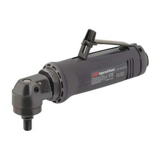
Ingersoll-Rand G1 Series Maintenance Information
Air grinder, die grinder, sander and belt sander
Hide thumbs
Also See for G1 Series:
- Product information (57 pages) ,
- Product information (56 pages) ,
- Product information (33 pages)
Summary of Contents for Ingersoll-Rand G1 Series
- Page 1 80234313 Edition 1 June 2006 Air Grinder, Die Grinder, Sander and Belt Sander Series G1 (Angle) Maintenance Information Save These Instructions...
- Page 2 WARNING Always wear eye protection when operating or performing maintenance on this tool. Always turn off the air supply and disconnect the air supply hose before installing, removing or adjusting any accessory on this tool, or before performing any maintenance on this tool. Note: When reading the instructions, refer to exploded diagrams in Parts Information Manuals when applicable (see under Related Documentation for form numbers).
- Page 3 12. Grasp the Arbor and pull the assembled Arbor out of the Bearing and End Plate. Remove the Front End Plate Angle Head. If the Wick (45) needs replacement, pull it Spacer (32) from the hub of the Rotor. out of the Angle Housing. 6.
- Page 4 8. Assemble Intake Cover onto Cylinder. There is a tab on when looking down length of Rotor, with threaded end the front of the Intake Cover that inserts into the Exhaust away. Seal and a tab that inserts into a hole in the Cylinder for 9.
- Page 5 9. Install the motor Clamp Nut (42), threaded end trailing, Assembly of the Sanding Arm (Belt Sander onto the motor end of the Angle Head. Spread the Clamp Models) Spacer (41) and install it, beveled end trailing, onto the motor end of the Angle Head against the Clamp Nut. NOTICE 10.
-
Page 6: Troubleshooting Guide
Troubleshooting Guide Troubleshooting Guide Trouble Probable Cause Solution Low power or low free Insufficient air pressure. Check air line pressure at the Inlet of the Tool. It speed must be 90 psig (6.2 bar/620 kPa). Clogged muffler elements. Disassemble the Inlet and remove Exhaust Diffuser to replace Mufflers for Rear Exhaust. -
Page 7: Related Documentation
Troubleshooting Guide Trouble Probable Cause Solution Rough operation/vibration Improper lubrication or dirt buildup. Disassemble the Tool and clean in a suitable cleaning solution. Assemble the Tool and inject 3 of the recommended oil into the Inlet and run the tool long enough to coat the internal parts with the oil. - Page 8 www.irtools.com Ingersoll Rand © 2006 Company...


Need help?
Do you have a question about the G1 Series and is the answer not in the manual?
Questions and answers