Advertisement
ASSEMBLY AND INSTALLATION
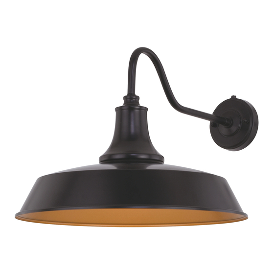
T0572
W
WARNING: Turn off the main power at circuit breaker before installing fixture.
AVERTISSEMENT: Coupez la source d'alimentation principale au panneau
central de disjoncteurs avant d'installer le luminaire.
NOTE: 1. Before installing, consult local electrical codes for wiring and grounding requirements.
2. READ AND SAVE THESE INSTRUCTIONS.
Hardware Package (included):
Cross Bar (A)
Headless screw (E)
House Grounding Wire
Outlet Box
Wire Connector (C)
Headless Screw (E)
Cross Bar (A)
Green Grounding Screw (D)
Mounting Screw (B)
Lock Nut (F)
Fixture Grounding Wire
Fixture Wire
Installation steps
Turn off the power at fuse or circuit box.
1. Thread two headless screws (E) through the cross bar (A), and then secure them with four lock nuts (F) (two on each
side of the cross bar (A).) Adjust the length of the headless screws (E) if necessary.
Note: Make sure the headless screws are lined up horizontally to make the fixture level.
2. Attach the cross bar (A) to the outlet box by using two mounting screws (B).
INSTRUCTIONS
Mounting Screw (B)
Lock Nut (F)
Photocell
Backplate
Rubber Pad (H)
Bolt Nut (G)
Wire Connector (C)
Bolt Nut (G)
Green Grounding Screw (D)
Rubber Pad (H)
Fixture
Socket
Socket Ring
Max.60W Type A Bulb
(not included)
191203
Shade
Advertisement
Table of Contents

Related Manuals for Vaxcel T0572


Summary of Contents for Vaxcel T0572
- Page 1 ASSEMBLY AND INSTALLATION INSTRUCTIONS T0572 WARNING: Turn off the main power at circuit breaker before installing fixture. AVERTISSEMENT: Coupez la source d’alimentation principale au panneau central de disjoncteurs avant d’installer le luminaire. NOTE: 1. Before installing, consult local electrical codes for wiring and grounding requirements.
- Page 2 3. Pull out the source wires from the outlet box. Make wire connections using wire connectors (C) as follows: • Connect the hot wire (usually black insulation) from the fixture to the black wire from the power source. • Connect the neutral wire (usually white insulation) from the fixture to the white wire from the power source. •...
- Page 3 The following parts are available for re-order if damaged or missing. Spare Parts List: Mounting Hardware 6200MM (1SET) Cross Bar (A) Mounting Screw (B) Wire Connector (C) Green Grounding Screw (D) Lock Nut (F) Bolt Nut (G) Rubber Pad (H) Headless screw (E) A: 14”...
Need help?
Do you have a question about the T0572 and is the answer not in the manual?
Questions and answers