Table of Contents
Advertisement
Quick Links
Advertisement
Table of Contents

Related Manuals for Kunbus Sercos Series


Summary of Contents for Kunbus Sercos Series
- Page 1 User manual Gateway component Sercos DO0227R00 • 6/28/2016...
-
Page 2: Table Of Contents
Table of Contents KUNBUS GmbH Table of Contents 1 General Information ........................ 3 1.1 Disclaimer.......................... 3 1.2 Notes Regarding this User Manual.................... 3 1.3 Validity ............................ 4 1.4 Limitation of Liability ........................ 4 1.5 Customer Service ........................ 4 2 Safe Use ............................ 5 2.1 User ............................ 5 2.2 Symbols............................. 5 3 Overview ............................ 6... -
Page 3: General Information
1.1 Disclaimer © 2016 KUNBUS GmbH, Denkendorf (Germany) The contents of this user manual have been prepared by KUNBUS GmbH with the utmost care. Due to technical development, KUNBUS GmbH reserves the right to change or replace the contents of this user manual without prior notice. -
Page 4: Validity
1.3 Validity This document describes the application of the KUNBUS Gateway with the product number: – PR100075, release 00 1.4 Limitation of Liability Warranty and liability claims will lapse if: – the product has been used incorrectly, – damage is due to non-observance of the operating manual, –... -
Page 5: Safe Use
2 Safe Use 2.1 User The Gateway may only be assembled, installed and put into operation by trained, qualified personnel. Before assembly, it is absolutely essential that this documentation has been read carefully and understood. Expertise in the following fields is assumed: –... -
Page 6: Overview
3 Overview 3.1 Functionality The KUNBUS Gateway is a protocol converter. It allows communication between networks with different protocols. Illustration 1: Functionality A Gateway consists of 2 gateway components that master one specific protocol each. You can combine these gateway components as you wish. -
Page 7: Control Elements
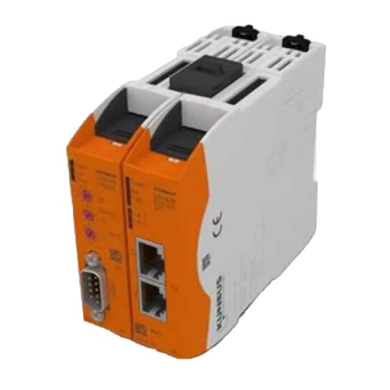
3.2 Control Elements Front view Illustration 2: Front view Status LEDs for signal display. 2 rotary coding switches for setting the station number. Fieldbus connection RJ45 socket for the connection to SERCOS and/or general LAN. Auto-Negotiation and Auto-MDI-X are supported. (2 pcs, s. figure top view) Gateway component Sercos 7 / 23... - Page 8 Illustration 3: Top Fieldbus connection RJ45 socket for connection to the fieldbus (2 pcs, see figure front view). Interconnect ports for interconnecting the gateway components. Locking clamps for securely attaching the gateway component to the DIN rail. 8 / 23 Gateway component Sercos...
- Page 9 Bottom Illustration 4: Bottom Mains connection with 24 V power supply Locking clamps for securely attaching the gateway component to the DIN rail. Gateway component Sercos 9 / 23...
-
Page 10: Status Leds
3.3 Status LEDs The signals of the status LEDs for SERCOS have the following meaning: Signal Meaning designation Power Gateway not running flashes, green Initialization phase not yet completed on, green All system components are functioning perfectly flashes, red Correctable error (e.g. second gateway component missing) Flashes, red and Factory reset is executed... -
Page 11: Installation
4 Installation 4.1 Preparations for Trouble-free Operation In the following section we have compiled some general information for you that is important for trouble-free operation. If you are already acquainted with this topic, you can skip to the next section. There, you will learn about which conditions are necessary for installing the gateway. - Page 12 Potential equalization Potential differences occur when devices are connected to different earths. These potential differences cause malfunctions. To prevent malfunctions, you have to route an equipotential equalization conductor. When doing so, bear in mind the following points: – Select an equipotential equalization conductor with low impedance. –...
-
Page 13: Requirements
4.2 Requirements The Gateway was designed for use in a control cabinet. ü The protection class of the control cabinet must be equivalent to at least IP54. ü For installation in the control cabinet you need a DIN rail 35 x 7.5 mm (EN50022). -
Page 14: Connecting Gateway Components
4.3 Connecting Gateway Components In order to attain a fully functional gateway, you have to interconnect both gateway components. ◦ Connect an interconnect port to each gateway component using the plug-in jumper (product number PR100204). ◦ Illustration 6: Connecting gateway components ð... -
Page 15: Installing A Gateway In The Control Cabinet
4.4 Installing a Gateway in the Control Cabinet ◦ Hold the raster element of the gateway on the DIN rail. ◦ Press down the locking elements towards the gateway. ◦ Make sure that the gateway is firmly attached to the DIN rail. Gateway component Sercos 15 / 23... -
Page 16: Connecting A Power Supply
4.5 Connecting a Power Supply To connect the gateway component to the power supply, you need a spring-loaded terminal (e.g. Metz-Connect SP995xxVBNC). You have to connect each gateway component separately to a power supply. Never interconnect functional earth and GND, otherwise the galvanic isolation between gateway GND and fieldbus ground will be removed. -
Page 17: Configuration
5 Configuration 5.1 Supported Size of the Process Data The gateway component for SERCOS supports process data up to a length of 250 bytes per direction. Of these 250 bytes, 4 bytes of control data (for Connection Control and I/O-Control/status) are reserved. Bear in mind that the maximum length of the process data is always NOTICE determined by the fieldbus with the shorter data length. - Page 18 Illustration 7: Coding switch The station address is set as a hexadecimal. Example: Setting the station number 18. Set switch x16 (1) to position "2". Set switch x1 (2) to position "1". The settings yield the hexadecimal value 0x12 and the decimal value 18 / 23 Gateway component Sercos...
-
Page 19: Sercos Configuration
5.3 Sercos Configuration Prerequisite: You are logged in as "Admin" on the webserver (s. section "Logging into Webserver"). Illustration 8: Settings for Sercos You can make the following settings for Sercos: Value Default Use Sercos Address 64 Device address for the gateway component. You can set an address in a value range between 1 and 511. -
Page 20: Server
6 Server 6.1 Web Server The gateway component contains an integrated web server. You can use this via Internet Explorer or Firefox. With the web server you can configure the gateway component for Sercos. 6.2 FTP Server The FTP server is necessary for updating HTML files of the web server and for transmitting firmware updates to the module. -
Page 21: Technical Data
7 Technical Data 7.1 Technical Data Dimensions Width 22.5 mm Height 96 mm Depth 110.4 mm Weight 90 g Electrical data Power supply 24 V DC Power consumption during operation 100 mA (cyclical data exchange) Status display Environmental conditions Ambient temperature 0 –... - Page 22 Device data You can find details on the following basic data in the device description file [SDDML]. Device Name KUNBUS Gateway Sercos3 Manufacturer Number 2000 Vendor Name KUNBUS GmbH Vendor Device ID PR100075 Device type Sercos III Slave Device Sercos Protocol V1.3.1...
- Page 23 Illustration 10: Front dimensions Gateway component Sercos 23 / 23...
Need help?
Do you have a question about the Sercos Series and is the answer not in the manual?
Questions and answers