
Related Manuals for Aalborg DPM Series


Summary of Contents for Aalborg DPM Series
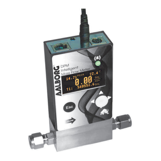
- Page 1 Technical Data Sheet No. TD-DPM- 520 Date of Issue: May 2020 OPERATING MANUAL Aalborg DPM Intelligent Digital Mass Flow Meters...
- Page 2 Aalborg® is a registered trademark of Aalborg Instruments & Controls. NOTE: Aalborg reserves the right to change designs and dimensions at its sole discretion at any time without notice. For certified dimensions, please contact Aalborg.
-
Page 3: Table Of Contents
TABLE OF CONTENTS Unpacking the DPM Mass Flow Meter........1.1 Inspect Package for External Damage........1.2 Unpack the Mass Flow Meter..........1.3 Returning Material for Repair..........2. Installation................. 2.1 Safety Instructions..............2.2 Primary Gas Connections............3. Electrical Connections............... 3.1 Power Supply Connections............ 3.2 Output Signals Connections.......... - Page 4 6.4.13.4 Submenu “Modbus Interface” (optional)....5 6.4.13.5 Relay Assignment............5 6.4.13.6 Analog Output Configuration........5 6.4.13.7 Status LED Settings..........5 6.4.13.8 Signal Conditioner Settings........5 6.4.14 Sensor Zero Calibration..........5 6.4.14.1 DP Sensor Zero Calibration........5 6.4.14.2 Start AP Auto Tare...........5 6.4.15 Submenu “Alarms and Diagnostic”....... 6.4.15.1 Alarm Event Register..........
-
Page 5: Unpacking The Dpm Mass Flow Meter
Mass Flow Meter directly, to request a Return Authorization Number (RAN). Equipment returned without a RAN will not be accepted. Aalborg reserves the right to charge a fee to the customer for equipment returned under warranty claims if the instruments are found, when examined and tested, to be free of warrantied defects. -
Page 6: Primary Gas Connections
CAUTION: DPM meters should not be used for monitoring oxygen gas unless specifically cleaned and prepared for such an application. For more information, contact your distributor or Aalborg. The DPMMassFlow Metercan be mounted inany position. It is not requiredto maintain straight runs of pipe upstream or downstream of the meter. - Page 7 CAUTION: For DPM07/17/37/47/57/67/77 series flow meters, the maximum pressure in the gas line must not exceed 120PSIG (8.3bar). Applying pressure above 120 PSIG (8.3 bar) will cause permanent damage to the differential pressure sensor. CAUTION: For DPM04/14/24/34/44/54 "BREEZE"Low Differential Pressure series flow meters, the maximum pressure in the gas line must not exceed 50PSIG (3.44bar).
-
Page 8: Electrical Connections
ELECTRICAL CONNECTIONS DPMisequippedwithan 8 pin-MiniDINpower,analog/relayoutput, communication interface connector. Table I explains the pin designations. See Figure 1 for a Pin Diagram. TABLE I: 8-PIN DESIGNATIONS AND NOTES FUNCTION NOTE Solid State SPST Relay NO Do not exceed SSR maximum voltage 48 (normally open) contact #1 AC peak/DC and maximum load current 400 Solid State SPST Relay NO... -
Page 9: Power Supply Connections
CAUTION: Generally, "Mini-DIN" Connector numbering patterns are standardized. There are, however, some connectors with nonconforming patterns, so the numbering sequence on your mating connector may or may not coincide with that shown in our pin configuration above. It is imperative that you match the appropriate wires in accordance with the correct sequence regardless of the particular numbers displayed on the mating connector. -
Page 10: Digital Communication Interface Connections
DPM series Mass Flow Meters are equipped with calibrated 0-5Vdc, 0-10Vdc or 4-20 mA output signals. This linear output signal represents 0-100% of the flow meter’s full scale range. The user may select the desired analog interface type using a local OLED/Joystick interface or via digital communication interface. -
Page 11: Specifications
Each DPM ordered with RS-232 interface option is supplied with default crossover foot long communication cable (AALBORG P/N: CBL-A232) DB9 female to stereo 3.5 mm Plug. If custom length cable is required, it can be assembled using the connection... - Page 12 Each DPM ordered with RS-485 interface option is supplied with a default 3-foot length of communication cable (AALBORG P/N: CBL-A485) Stereo 3.5 mm plug to stripped wires. If custom length cable is required, it can be assembled using the connection...
- Page 13 FI I G G U U R R E 3: D D P P M R R S S -4 4 8 8 5 C C O O M M M M U U N N I I C C AT T I I O O N N I I N N T T E E R R F F A A C C E C C O O N N N N E E C C T T I I O O N N S When the DPM device is set as the last device on the long RS-485 bus segment, the 120 bus termination resistor must be connected between the RS-485 (+)
- Page 14 P P R R I I N N C C I I P P L L E O O F F O O P P E E R R AT T I I O O N N The DPM series flow meters integrate precision a differential pressure sensor which accurately measures pressure drop across the special restriction flow element (RFE).
- Page 15 Kalrez® O-rings are optional), high temperature polyamide, alumina ceramic, epoxy, silicone, glass, gold. CAUTION: ® Aalborg makes no expressed or implied guarantees of corrosion resistance of mass flow meters as pertains to different flow media reacting with any components of the meters. It is solely the customer’s responsibility to select the model best suited for a...
-
Page 16: Dpm Accessories
IN N L L E E T T A A N N D O O U U T T L L E E T T C C O O N N N N E E C C T T I I O O N N S S : : DPM04/07 10-32 female thread, DPM14/17/37 1/8"... - Page 17 POWER SUPPLIES MODEL NO. DESCRIPTION Power Supply, 110 V / 12 Vdc / North America. PS-GFM-110NA-2 PS-GFM-110NA-4 Power Supply, 110 V / 24 Vdc / North America. Power Supply, 220 V / 12 Vdc / Europe. PS-GFM-230EU-2 Power Supply, 220 V / 24Vdc / Europe. PS-GFM-230EU-4 PS-GFM-240UK-2 Power Supply 240 V / 12 Vdc / United Kingdom.
- Page 18 TABLE IV: PRESSURE DROPS MA A X X I I M M U U M M P P R R E E S S S S U U R R E E D D R R O O P P FL L O O W R R A A T T E E MO O D D E E L L [s s t t d l l i i t t e e r r s s / / m m i i n n ]...
- Page 19 Fi i g g u u r r e 4 4 : : DP P M M fir r s s t B B a a n n n n e e r r S S c c r r e e e e n n F F w w : A A 0 0 0 0 1 1 T T b b l l : : A A 0 0 0 0 1 1 C C O O M M : : R R S S 2 2 3 3 2 A A d d d d : : 1 1 1 1...
- Page 20 6. . 3 3 M e e t t e e r P P r r o o c c e e s s s I I n n f f o o r r m m a a t t i i o o n ( ( P P I I ) ) s s c c r r ee e n n s Based on meter configuration, different parameters may be displayed in the Process Information (PI) screen by moving the control joystick (see Figure 7) Up or Down (DN).
- Page 21 PI Screen #1 (Pressure, Temperature, PSIA 22 2 . . 7 7 7 7 25 5 . . 7 Mass Flow Rate, Totalizer #1) Sm m l l 0. . 0 0 0 mi i n n T1 1 : : 14 4 7 7 2 2 6 6 . . 0 0 PI Screen #2 (Pressure, Temperature, PSIA 25 5 .
- Page 22 6. . 4 4 L L o o c c a a l U U s s e e r r I I n n t t e e r r f f a a c c e M M e e n n u u S S t t r r u u c c t t u u r r e The diagram in Figure 13 gives a general overview of the standard top-level display menu structure (when running firmware version A001).
- Page 23 NOTE: By default, the device is shipped from the factory with the Program Protection (PP) password set to Zero (PP Disabled). Once the correct password is entered, the Program Protection is turned off until the unit is powered up again. 6.
- Page 24 In order to protect device configuration parameters when changing the PP password, the old PP password must first be entered. Onceoldand newpasswordsare entered, thefirmware will prompt with a confirmation message (see Figure 12) that the new password has been saved: Ne e w w P P P P P P a a s s s s w w o o r r d d ha a s s b b e e e e n n s s a a v v e e d PP P P a a s s s s w w o o r r d d i i s s C C h h a a n n g g e e d...
- Page 25 TABLE VI: LIST OF SUPPORTED MASS FLOW UNITS OF MEASURE Number Mass Flow Rate Totalizer Volume Units Description Units STANDARD Percent of Full Scale SuL/min Microliters per minute SmL/sec Milliliter per second SmL/min Milliliters per minute SmL/hr Milliliter per hour SL/sec Liter per second SL/min...
- Page 26 TABLE VII: LIST OF SUPPORTED VOLUMETRIC FLOW UNITS OF MEASURE Number Flow Rate Units Totalizer Volume Units Description Percent of Full Scale uL/min Microliters per minute mL/sec Milliliter per second mL/min Milliliters per minute mL/hr Milliliter per hour L/sec Liter per second L/min Liter per minute L/hr...
- Page 27 NOTE: Program the Measuring Units first because subsequent menus may be based on the units selected. Once Flow Unit of Measure is changed, the Totalizer’s Unit of Measure will be automatically updated. 6. . 4 4 . . 5 5 “ “ S S u u b b m m e e n n u u U U s s e e r r - - D D e e f i f in n e e d U U n n i i t t s s ”...
- Page 28 Figure 13 DPM Upper Levels Menu Structure...
- Page 29 6. . 4 4 . . 6 6 S S u u b b m m e e n n u " " S S e e l l e e c c t G G a a s s " " The currently active gas can be selected by the user via OLED/joystick or digital communication interface.
- Page 30 TABLE X: Standard Pure Non-Corrosive Gases A A l l l D D a a t t a a f f o o r S S ta a n n d d a a r r d d C C o o n n d d i i t t i i o o n n s s ( ( 7 7 0 ° ° F F a a n n d 1 1 4 4 . . 6 6 9 9 6 6 P P S S I I A A ) Ab b s s o o l l u u t t e Ga a s s Sh h o o r r t t...
- Page 31 TABLE XI: Bioreactor Gases A A l l l D D a a t t a a f f o o r S S t t a a n n d d a a r r d d C C o o n n d d i i t t i i o o n n s s ( ( 7 7 0 ° ° F F a a n n d 1 1 4 4 . . 6 6 9 9 6 6 P P S S I I A A ) Ab b s s o o l l u u t t e Ga a s s Sh h o o r r t t...
- Page 32 TABLE XII: Breathing Gases A A l l l D D a a t t a a f f o o r S S ta a n n d d a a r r d d C C o o n n d d i i t t i i o o n n s s ( ( 7 7 0 ° ° F F a a n n d 1 1 4 4 . . 6 6 9 9 6 6 P P S S I I A A ) Ab b s s o o l l u u t t e Ga a s s Sh h o o r r t t...
- Page 33 T T ABLE XIV: Fuel Gases A A l l l D D a a t t a a f f o o r S S ta a n n d d a a r r d d C C o o n n d d i i t t i i o o n n s s ( ( 7 7 0 ° ° F F a a n n d 1 1 4 4 . . 6 6 9 9 6 6 P P S S I I A A ) Ab b s s o o l l u u t t e Sh h o o r r t t De e n n s s i i t t y y g / l...
- Page 34 TABLE XV: Laser Gases A A l l l D D a a t t a a f f o o r S S t t a a n n d d a a r r d d C C o o n n d d i i t t i i o o n n s s ( ( 7 7 0 ° ° F F a a n n d 1 1 4 4 . . 6 6 9 9 6 6 P P S S I I A A ) Ab b s s o o l l u u t t e Ga a s s Sh h o o r r t t...
-
Page 35: Submenu "User-Defined Mixture
TABLE XVIII: Welding Gases A A l l l D D a a t t a a f f o o r S S t t a a n n d d a a r r d d C C o o n n d d i i t t i i o o n n s s ( ( 7 7 0 ° ° F F a a n n d 1 1 4 4 . . 6 6 9 9 6 6 P P S S I I A A ) Ab b s s o o l l u u t t e Ga a s s Sh h o o r r t t... - Page 36 En n t t e e r r M M i i x x t t u u r r e N N a a m m e e : _ M _ yM _ _ i _ x 1 _ _ Us s e e to C C h h a a n n g g e e C C a a s s e e Pr r e e s s s s E E n n t t W W h h e e n n D D o o n n e e...
- Page 37 MyMix1 G:0 Tot:0.00% G1 Ar 0.00% 0.00% 0.00% 0.00% 0.00% Save, Esc to Exit Figure 19: G1 Component with Selected Gas Once the gas is selected for component G1, the screen shown in Figure 19 will appear. To select the ratio for component G1, press Right. The screen shown in the top of Figure 20 will appear.
- Page 38 MyMix1 G:0 Tot: 22.00% MyMix1 G:0 Tot: 10.00% G1 Ar 10.00% G1 Ar 10.00% 0.00% G2 He 12.00% 0.00% 0.00% 0.00% 0.00% 0.00% 0.00% Save, Esc to Exit Save,EsctoExit MyMix1 G:0 Tot:100.0% MyMix1 G:0 Tot: 10.00% G1 Ar 10.00% G1 Ar 10.00% G2 He 12.00%...
- Page 39 MyMix1 Add Mixture: 19 Free Figure 23: “User-Defined Mixture” Menu Selection with new MyMix1 Mixture Any saved mixture can be edited by the user. In order to edit a saved mixture, highlight it using Up and Down and then pressing Left. The confirmation message shown in Figure 24 will appear.
- Page 40 The following settings are available for the Flow Alarm (see Figure 13): a) Flow Alarm Mode (Tabular entry) This function determines whether the Flow Alarm is Enabled or Disabled, the only two selections available. The default entry is Disabled. Alarm Mode selections can be set with the joystick UP and DN buttons, and are accepted by pressing the joystick equivalent of the ENT button.
-
Page 41: Submenu "Gas Pressure Alarm
e) Flow Alarm Power On Delay (Numerical entry) Sometimes it is convenient to enable the Flow Alarm only after a specified power-up delay interval. The “Flow Alarm Power On Delay” option allows the user to set a specified time interval which must elapse from the moment of the device power-up event before the Flow Alarm function will be activated. - Page 42 b) Low Pressure Alarm (Numerical entry) The limit of required Low Pressure Alarm value can be entered in currently selected pressure units, in increments of 0.1% of the pressure full scale range from 0.0 to 99.9 . If a Low Alarm occurs, and SSR output is assigned to the Low Pressure Alarm event (see Section 6.4.13.5) the SSR output will be activated when the pressure is less than the Low Pressure Alarm value.
- Page 43 3600 seconds. The default value is 0: no delay. f) Pressure Alarm Action Latch (Tabular entry) The Pressure Alarm Action Latch settings control the Latch features. If SSR output is assigned to the Pressure Alarm event, in some cases the Pressure Alarm Latch feature may be desirable.
- Page 44 The Low Temperature Alarm condition is also indicated on the corresponding Process Information Screen by alternating every second between units of measure and the “L” alert, meaning Low. NOTE: The value of the Low Pressure Alarm must be less than the value of the High Pressure Alarm.
- Page 45 Two settings are available: Disabled or Enabled. By default, the Temperature Alarm is non-latching. This means that the Alarm Action is indicated only if the monitored Temperature reading exceeds the user- specified conditions. 6. . 4 4 . . 1 1 1 To o t t a a l l i i z z e e r r s S S e e t t t t i i n n g g s s The DPM provides the user with two independent Programmable Flow Totalizers.
- Page 46 is not required, set “Totalizer Action Volume” value to zero; this is the default setting. d) TotalizerPowerOnDelay(Numericalentry) Sometimes it is convenient to start the Totalizer only after aspecified power-up delay interval. Mass flow meters require some warm-up time from the power-up event in ordertostabilizetheprocessvariableoutputandto getanaccuratereading.
- Page 47 ************************** Totalizer has been reset ************************** Press any key... Figure 26: Totalizer Reset Confirmation A local maintenance push button is available to manually reset the Totalizer in the field for DPM meters without the OLED/joystick option. The maintenance push button is located on the left side of the flow meter (see Section 6.5 “Multi-Functional Push-Button Operation”).
- Page 48 The OLED/joystick interface and digital communication interface commands are provided to: Enable/Disable Pulse Output Start Pulse Output at a preset flow rate (0.0 - 100.0% FS) Configure Unit/Pulse value (in current engineering units) Configure Pulse Active On Time (50 - 6553 ms) NOTE: The Pulse Output minimum Active On time is 50 milliseconds (0.05 second).
- Page 49 St t a a n n d d a a r r d Te e m m p p e e r r a a t t u u r r e e St t a a n n d d a a r r d P P r r e e s s s s u u r r e e No o r r m m a a l Te e m m p p e e r r a a t t u u r r e e No o r r m m a a l P P r r e e s s s s u u r r e e Standard Temperature and Normal Temperature menu selections allow the...
- Page 50 Th h e e f f o o l l l l o o w w i i n n g s s e e t t t t i i n n g g s s a a r r e a a v v a a i i l l a a b b l l e f f o o r O O L L E E D D D D i i s s p p l l a a y y : : a a ) ) D D i i s s p p l l a a y M M o o d d e e This option determines whether the display screens are in static (manual control) or dynamic (automatic sequencing) mode.
- Page 51 NOTE: By default, the brightness level is set to 127 which is the optimal level for room temperature (20 °C or 70 °F). e) OLED Screensaver Mode OLED is subject to burn-in. It can retain images on the screen temporarily and, in some cases even permanently if it is left static for too long.
- Page 52 NOTE: If Screensaver mode is active and has been changed, new settings will be activated in the next Screensaver cycle (after the Esc button or joystick interface was activated to disable the currently active screensaver). The OLED “Screensaver Brightness Level” parameter is only applicable for “Low Brightness”...
- Page 53 NOTE: Before changing the communication interface type, make sure that the host device (PC or PLC) has the same interface type. Connecting the instrument to the wrong communication interface may cause damage or result in faulty operation of the electronics circuitry. b b ) ) B B a a u u d d R R a a t t e e S S e e t t t t i i n n g g s s ( ( T T a a b b u u l l a a r e e n n t t ry y ) This option determines the device’s digital communication interface speed (Baud rate).
- Page 54 PLC to read and write directly to registers containing the meter’s parameters (see technical document TD-DPMCMOD-0118 “Modbus RTU slave interface for AALBORG digital mass flow instruments” for a detailed description of supported Modbus functions and registers). The following parameters are available for “Modbus Settings” (see Figure 1 ): a a ) ) D D e e v v i i c c e e I I D D ( ( A A d d d d r r e e s s s s ) ( ( N N u u m m e e r r i i c c a a l l e e n n t t r r y y ) Decimal representation ranges from 1 to 247.
- Page 55 9 9 6 6 0 0 0 0 1 1 9 9 2 2 0 0 0 3 3 8 8 4 4 0 0 0 5 5 7 7 6 6 0 0 0 1 1 1 1 5 5 2 2 0 0 0 0 By default, the device is shipped from the factory with its baud rate set at 9600.
-
Page 56: Analog Output Configuration
6. . 4 4 . . 1 1 3 3 . . 6 A A n n a a l l o o g g O O u u t t p p u u t t C C o o n n f i f ig g u u r r a a t t i i o o n The DPM series Mass Flow Meters are equipped with calibrated 0-5Vdc, 0- 10Vdc, and 4-20 mA output signals. - Page 57 NOTE: The analog outputs available in the DPM meter were calibrated at the factory. There is no need to perform analog output calibration unless the analog to digital converter (DAC) IC, output amplifier IC, or passive components from analog output circuitries were replaced or your factory customer support representative suggested recalibration.
- Page 58 6. . 4 4 . . 1 1 3 3 . . 7 S S t t a a t t u u s s L L E E D S S e e t t t t i i n n g g s s DPM series Mass Flow Meters are equipped with dual color LED which allows signaling a variety of different events with combinations of three colors (red, green and amber) and a specific time pattern.
- Page 59 3. Monitoring Alarm Events only (any active Alarm event will trigger LED indication): GREEN/OFF (alternating every second) 4. Monitoring Diagnostic Events only (any active Diagnostic event will trigger LED indication): RED/OFF (alternating every second) 5. Test and Configuration Communication Interface Monitoring: 5.1 Data Received (RX activity) RED LED flashing momentarily (about 200 ms or less) 5.2 Data Transmitted (TX activity) GREEN LED flashing momentarily (about...
-
Page 60: Sensor Zero Calibration
Shut off the gas flow into the DPM meter. To ensure that no seepage or leaking occurs into the meter, it is good practice to temporarily disconnect the gas source. The Auto Zero may be initiated locally using optional OLED/joystick interface (see Figure 1 ) or by pressing the multi-functional maintenance push button located on the left side of the meter, or via digital communication interface (see Figure 4 : DPM Interface Connectors and Maintenance Push... - Page 61 T T h h e st t a a t t u u s L L E E D w w i i l l l l r r e e t t u u r r n n t t o o a c c o o n n s s t t a a n n t t G G R R E E E E N l l i i g g h h t a a n n d t t h h e s s c c r r e e e e n n b b e e l l o o w w w i i l l l l a a p p p p e e a a r r : *********************** AUTO ZERO IS DONE!
-
Page 62: Alarm Event Register
NOTE: The AP Sensor Tare procedure requires high accuracy (at least 0.2% of reading) absolute pressure sensor reference standard. The AP sensor Tare result will be as accurate as your reference absolute pressure sensor is. To start the AP sensor Tare procedure locally using the OLED/joystick interface, select “Sensor Zero Calibration”... - Page 63 6. . 4 4 . . 1 1 5 5 . . 1 A A l l a a r r m E E v v e e n n t R R e e g g i i s s t t e e r r Th h e e f f o o l l l l o o w w i i n n g a a l l a a r r m e e v v e e n n t t s s a a r r e s s u u p p p p o o r r t t e e d d : : TABLE XIX: ALARM EVENTS REGISTER EVENT NUMBER...
- Page 64 Al l r r m m E E v v e e n n t t s S S t t a a t t u u s s : 0 No A A c c t t i i v v e e A A l l a a r r m m s s Figure 33: Alarm Events Register (with no alarms) A typical display with two active Alarm Events is shown in Figure 34: Al l r r m m E E v v e e n n t t s S S t t a a t t u u s s : 2...
- Page 65 A A l l a a r r m E E v v e e n n t t s s M M a a s s k k R R e e g g : : 2 - R R a a n n g g e b b / / w H H - - L [ [ * * ] 3 - To o t t # # 1 1 >...
- Page 66 To disable a latch feature, the corresponding asterisk must be removed. Use the ENT button to accept and save new Latch Alarm Event Register settings in the meter’s nonvolatile memory. d) Reset Status Alarm Event Register (Tabular entry) The Status Alarm Event Register can be reset by selecting the “Reset Alarm Event Reg”menu option.
- Page 67 6. . 4 4 . . 1 1 5 5 . . 2 D D i i a a g g n n o o s s t t i i c c E E v v e e n n t t s s R R e e g g i i s s t t e e r r Th h e e f f o o l l l l o o w w i i n n g a a l l a a r r m e e v v e e n n t t s s a a r r e s s u u p p p p o o r r t t e e d d : : TABLE XX: DIAGNOSTIC EVENTS REGISTER OLED BIT...
- Page 68 Di i a a g g E E v v e e n n t t s S S t t a a t t u u s s : 0 No A A c c t t i i v v e e E E v v e e n n t t s s Figure 39: Diagnostic Events Status Register (no active events) A typical display with two active Diagnostic events is shown below: Di i a a g g E E v v e e n n t t s S S t t a a t t u u s s : 2...
- Page 69 In the example shown above, latch features for all events except #0 are disabled. In order to change Mask Diagnostic Event Register settings, the user houls select the desired event with the joystick UP and DN buttons, then press the RIGHT button. The asterisk will appear in or disappear from the brackets to the right of the selected event.
- Page 70 Reset DiagEvents Reg.: DO YOU WANT RESET EVENT REG? Figure 43: Resetting Diagnostic Events Register When you select the “YES” option, the Event Register will be reset and the following confirmation screen will appear: *********************** Event Reg. Has been reset! *********************** Press any Key...
- Page 71 6. . 4 4 . . 1 1 5 5 . . 4 Te e m m p p e e r r a a t t u u r r e e S S e e n n s s o o r r s D D i i a a g g n n o o s s t t i i c c ( ( r r e e a a d o o n n l l y y ) This menu selection provides raw or average (filtered) ADC counts for gas temperature and pressure sensor temperature readings, which may be useful for Digital Signal Processing (DSP) troubleshooting (read only).
- Page 72 6. . 4 4 . . 1 1 5 5 . . 6 R R e e f f e e r r e e n n c c e Vo o l l t t a a g g e a a n n d D D S S P C C a a l l c c u u l l a a t t i i o o n D D i i a a g g n n o o s s t t i i c (r r e e a a d d o o n n l l y y ) This menu selection provides information about current 2.5Vdc reference voltage value as well as different parameters of the Temperature/Pressure...
- Page 73 FIGURE 49: DPM INTERFACE CONNECTORS AND MULTI-FUNCTION PUSH-BUTTON ACCESS HOLE See Table XXI on the following page for explanations.
- Page 74 TABLE XXI: LED Indications using the Multi-Function Push-Button During Normal Running Mode STATUS LED TIME INSTRUMENT ACTION INDICATION PUSHED Amber flashing On/Off Pressing a switch briefly (<6 sec) will not cause every 2 seconds seconds unwanted actions from the device but will Com.
-
Page 75: Maintenance
Remove debris as necessary. If the blockage still exists, contact Aalborg or your local distributor to arrange for repair or cleaning service. -
Page 76: Recalibration
Mass Flow Meters using NIST-traceable precision calibrators under strictly controlled conditions. NIST-traceable calibrations are available. CAUTION: DPM flow meters can be only calibrated by Aalborg Instruments' Flow Calibration Laboratory or an Aalborg authorized trained and certified calibration facility. 9 RS-235/RS-485 SOFTWARE INTERFACE COMMANDS 9. - Page 77 NOTE: The default RS-485 address for all units is 11. Never submit the start character with a two-character hexadecimal device address for the RS-232 option. Several examples of commands are shown below. All assume that the DPM meter has been configured for decimal address 18 (12 hex) on the RS-485 bus: 1.
- Page 78 NOTE: Do not assign the same RS-485 address to two or more devices on the same RS-485 bus. If two or more devices with the same address are connected to one RS-485 network, a communication collision on the bus will result, leading to communication errors.
- Page 79 AALBORG DPM ASCII SOFTWARE INTERFACE COMMANDS Note: An “*” indicates power up default settings. An “**”indicates optional feature not available on all models.
- Page 99 UART Error Codes: 1 – Command Not Supported or Back Door is not enabled. 2 – Wrong# of Arguments 3 – Address is Out of Range (MR or MW commands) 4 – Wrong# of the characters in the Argument 5 – Attempt to alter Write-Protected Area in the EEPROM 6 –...
-
Page 100: Common Conditions
10 0 . . T T R R O O U U B B L L E E S S H H O O O O T T I I N N G 10 0 . . 1 C C o o m m o o n n C C o o n n d d i i t t i i o o n n s s Your DPM Mass Flow Meter was thoroughly checked at numerous quality control points during and after manufacturing and assembly... - Page 101 NO. INDICATION LIKELY REASON SOLUTION OLED Display reading Output 0-5Vdc Return DPM to factory for repair. does correspond to the schematic is burned correct flow range, but out or damaged. 0-5Vdc output signal Analog flow output Restore original EEPROM scale does not change scale and offset and offset variable or perform...
- Page 102 NO. INDICATION LIKELY REASON SOLUTION The error between 1. Instruments may be 1. Check that both instruments DPM mass flow configured to measure are configured to measure the reading and different Gas. same Gas. another meter 2. Other meter mass flow 2.
- Page 103 10 0 . . 3 Te e c c h h n n i i c c a a l l A A s s s s i i s s t t a a n n c c e e Aalborg Instruments will provide technical assistance over the phone to qualified repair personnel.
- Page 104 AP P P P E E ND D I I X I: CO O M M P P O O N N E E N N T T D D I I A A G G R R A A M TO O P P C C O O M M P P O O N N E E N N T S S I I D D E E...
- Page 105 BO O T T T T O O M C C O O M M P P O O N N E E N N T S S I I D D E E...
- Page 106 AP P P P EN N D D I I X X I I I I : DI I M M E E N N S S I I O O N N A A L L D D R R AW W I I N N G G S...
- Page 108 Anything to the contrary will automatically void the liability of Aalborg and the provisions of this warranty. Defective products will be repaired or replaced solely at the discretion of Aalborg at no charge.
- Page 109 APPENDIX IV: INDEX OF FIGURES Figure # Title Page DPM 8-pin Mini-DIN Connector Configuration DPM RS-232 Communication Interface Connections DPM RS-485 Communication Interface Connections DPM First Banner Screen DPM Firmware and Communication Interface Information Screen DPM Initial Process Information Joystick DPM Process Information Screens Program Protection Screen Program Protection Password Screen...
- Page 110 Figure # Title Page Diagnostic Events Mask Register Diagnostic Events Latch Register Resetting Diagnostic Events Register Confirmation of Diagnostic Events Register Reset Pressure Sensors ADC Diagnostic Temperature Sensors Diagnostics Analog Output and PO Queue Diagnostic Reference Voltage and DSP Calculation Diagnostic DPM Interface Connectors and Multi-Function Push-Buston Access Hole...
-
Page 111: Troubleshooting Guide
Chromatography Gases Fuel Gases Laser Gases Concentrator Gases XVII Stack Gases XVIII Welding Gases Alarm Events Register Diagnostic Events Register LED Indications using the Multi-Function Push- Button During Normal Running Mode XXII Aalborg DPM ASCII Software Interface Commands XXIII Troubleshooting Guide...
Need help?
Do you have a question about the DPM Series and is the answer not in the manual?
Questions and answers