
Subscribe to Our Youtube Channel
Related Manuals for Aalborg XFM Series


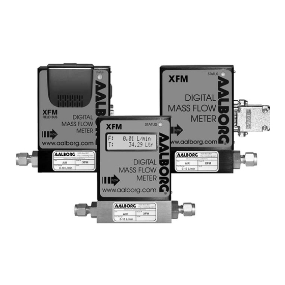
Summary of Contents for Aalborg XFM Series
- Page 1 Technical Data Sheet No. TD0701M Rev. D Date of Issue: November 2016 OPERATING MANUAL XFM DIGITAL MASS FLOW METERS...
-
Page 2: Table Of Contents
TABLE OF CONTENTS 1. UNPACKING THE XFM MASS FLOW METER......... Inspect Package for External Damage..........Unpack the Mass Flow Meter............... Returning Merchandise for Repair............2. INSTALLATION..................Primary Gas Connections..............Electrical Connections..............2.2.1 Power Supply Connections.............. 2.2.2 Output Signals Connections.............. 2.2.3 Communication Parameters and Connections........3. - Page 3 Common Conditions............... Troubleshooting Guide..............Technical Assistance............... CALIBRATION CONVERSIONS FROM REFERENCE GASES....APPENDIX I AALBORG XFM EEPROM Variables........APPENDIX II INTERNAL USER SELECTABLE GAS FACTOR TABLE (INTERNAL "K" FACTORS)............APPENDIX III GAS FACTOR TABLE ("K" FACTORS)........APPENDIX IV COMPONENT DIAGRAM............APPENDIX V DIMENSIONAL DRAWINGS..........
-
Page 4: Unpacking The Xfm Mass Flow Meter
UNPACKING THE XFM MASS FLOW METER Inspect Package for External Damage Your XFM Mass Flow Meter was carefully packed in a sturdy cardboard carton, with anti-static cushioning materials to withstand shipping shock. Upon receipt, inspect the package for possible external damage. In case of external damage to the package contact the shipping company immediately. - Page 5 CAUTION: It is the user’s responsibility to determine if the instrument is appropriate for their OXYGEN application and for specifying O2 cleaning service if required. Aalborg is not liable for any damage or personal injury, whatsoever, resulting from the use of this instrument for oxygen.
-
Page 6: Electrical Connections
ON. Wiring error may cause damage or faulty operation. XFM series Mass Flow Meters are equipped with either calibrated 0-5 or cali- brated 4-20 mA output signals (jumper selectable). This linear output signal rep- resents 0-100% of the flow meter’s full scale range. -
Page 7: Communication Parameters And Connections
2.2.3 Communication Parameters and Connections The digital interface operates via RS485 (optional RS-232 or Profibus DP avail- able) and provides access to applicable internal data including: flow, CPU tem- perature reading, auto zero, totalizer and alarm settings, gas table, conversion factors and engineering units selection, dynamic response compensation and lin- earization table adjustment. - Page 8 DC Power cable length may not exceed 9.5 feet (3 meters). Use of the XFM flow transducer in a manner other than that specified in this manual or in writing from Aalborg, may impair the protection provided by the equipment.
-
Page 9: Principle Of Operation
PRINCIPLE OF OPERATION The stream of gas entering the Mass Flow transducer is split by shunting a small portion of the flow through a capillary stainless steel sensor tube. The remainder of the gas flows through the primary flow conduit. The geometry of the primary con- duit and the sensor tube are designed to ensure laminar flow in each branch. -
Page 10: Specifications
SPECIFICATIONS FLOW MEDIUM: Please note that XFM Mass Flow Meters are designed to work only with clean gases. Never try to measure flow rates of liquids with any XFM. CALIBRATIONS: Performed at standard conditions [14.7 psia (101.4 kPa) and 70 (21.1 C)] unless otherwise requested or stated. -
Page 11: Ce Compliance
CAUTION: Aalborg makes no expressed or implied guarantees of corrosion resistance of mass flow meters as pertains to different flow media reacting with components of meters. It is the customers' sole responsibility to select the model suitable for a particular gas based on the fluid contacting (wetted) materials offered in the different models. - Page 12 FLOW RANGES TABLE I XFM 17 LOW FLOW MASS FLOW METER* scc/min [N std liters/min [N CODE CODE 0 to 5 0 to 1 0 to 10 0 to 2 0 to 20 0 to 5 0 to 50 0 to 10 0 to 100 0 to 200 0 to 500...
- Page 13 TABLE IV PRESSURE DROPS MAXIMUM PRESSURE DROP FLOW RATE MODEL [std liters/min] [mm H [psid] [kPa] XFM 17 up to 10 0.18 1.275 XFM 37 XFM 47 XFM 57 XFM 67 XFM 77 1000 TABLE V APPROXIMATE WEIGHTS MODEL WEIGHT SHIPPING WEIGHT XFM 17 transmitter 2.20 lbs.
-
Page 14: Operating Instructions
When applying power to a flow meter within the first two seconds, you will see on the LCD display: the product name, the software version, and revision of the EEP- ROM table (applicable for LCD option only). AALBORG XFM 485 S: Ver1.4 Rev.A0... -
Page 15: Swamping Condition
Note: Allow the Digital Mass Flow Meter to warm-up for a MINIMUM of 6 minutes. During initial powering of the XFM transducer, the flow output signal will be indi- cating a higher than usual output. This is an indication that the XFM transducer has not yet attained its minimum operating temperature. -
Page 16: Xfm Parameters Settings
XFM Parameters Settings 5.3.1 Engineering Units Settings The XFM Mass Flow Meter is capable of displaying flow rate with 23 different Engineering Units. Digital interface commands (see paragraph 8.3 ASCII Command Set “XFM SOFTWARE INTERFACE COMMANDS”) are provided to: get currently active Engineering Units set desired Engineering Units. -
Page 17: Gas Table Settings
Note: Once Flow Unit of Measure is changed, the Totalizer’s Volume/Mass based Unit of Measure will be changed automatically. 5.3.2 Gas Table Settings. The XFM Mass Flow Meter is capable of storing calibration data for up to 10 dif- ferent gases. Digital interface commands are provided to: get currently active Gas Table number and Gas name set desired Gas Table. -
Page 18: Flow Alarm Settings
Local maintenance push button is available for manual Totalizer reset on the field. The maintenance push button is located on the right side of the flow meter inside the maintenance window above the 15 pin D-connector (see Figure c-1 “XFM configuration jumpers”). -
Page 19: Relay Assignment Settings
Latch Mode- Controls Latch feature when Relays are assigned to Alarm event. Following settings are available: 0 - Latch feature is disabled for both relays 1 - Latch feature is enabled for Relay#1 and disabled for Relay#2 2 - Latch feature is enabled for Relay#2 and disabled for Relay#1 3 - Latch feature is enabled for both relays. -
Page 20: K Factors Settings
5.3.6 K Factors Settings Conversion factors relative to Nitrogen for up to 36 gases are stored in the XFM (see APPENDIX II). In addition, provision is made for a user-defined conversion factor. Conversion factors may be applied to any of the ten gas calibrations via digital interface commands. - Page 21 AUTOZERO IS ON! Figure b-6: XFM Screen in the beginning of Auto Zero procedure. The Auto Zero procedure normally takes 1 - 2 minutes during which time the DP Zero counts and the Sensor reading changes approximately every 3 to 6 seconds. AUTOZERO IS ON! DP: 512 Figure b-7: XFM during the Auto Zero procedure.
-
Page 22: Self Diagnostic Alarm
“ASCII Command Set”). Analog Output Signals configuration XFM series Mass Flow Meters are equipped with calibrated 0-5 Vdc and 4-20 mA output signals. The set of the jumpers (J7A, J7B, J7C) located on the right side of the flow meter, inside of the maintenance window above the 15 pin D-connector (see Figure c-1 “XFM configuration jumpers”... -
Page 23: Maintenance
If periodic calibrations are required, they should be performed by qualified per- sonnel and calibrating instruments, as described in section 7. It is recommended that units are returned to Aalborg® for repair service and calibration. CAUTION: TO PROTECT SERVICING PERSONNEL IT IS... -
Page 24: Flow Path Cleaning
Flow Path Cleaning Before attempting any disassembly of the unit for cleaning, try inspecting the flow paths by looking into the inlet and outlet ends of the meter for any debris that may be clogging the flow through the meter. Remove debris as necessary. If the flow path is clogged, proceed with steps below. -
Page 25: Xfm 57/67/77 Models
DESCRIBED IN THIS SECTION, WILL VOID ANY CALIBRATION WARRANTY APPLICABLE. Flow Calibration Aalborg® Instruments' Flow Calibration Laboratory offers professional calibration support for Mass Flow Meters using precision calibrators under strictly controlled conditions. NIST traceable calibrations are available. Calibrations can also be per- formed at customers' site using available standards. -
Page 26: Gas Calibration Of Xfm Mass Flow Meters
It is best to calibrate XFM transducers to actual operating conditions. Specific gas calibrations of non-toxic and non-corrosive gases are available for specific conditions. Please contact your distributor or Aalborg® for a price quota- tion. It is recommended that a flow calibrator be used which has at least four times bet- ter collective accuracy than that of the Mass Flow Meter to be calibrated. -
Page 27: Zero Check/Adjustment Adjustment
7.2.2 ZERO Check/Adjustment Using Aalborg® supplied calibration and maintenance software open Back Door access: Query/BackDoor/Open When software prompts with Warning, click the [YES] button. This will open the access to the rest of the Query menu. Start Sensor Compensated Average reading: Query/Read/ SensorCompAverage This will display Device Sensor Average ADC counts. - Page 28 Once 100% F.S. calibration is completed, the user can proceed with calibration for another 9 points of the linearization table by using the same approach. Note: It is recommended to use Aalborg® supplied calibration and maintenance software for gas table calibration. This software includes an automated calibration procedure which may radically simplify reading and writing for the EEPROM linearization table.
-
Page 29: Analog Output Calibration Of Xfm Mass Flow Meters
Gas independent table will VOID calibration warranty supplied with instrument. Note: It is recommended to use the Aalborg® supplied calibration and maintenance software for analog output calibration. This software includes an automated calibration procedure which may radically simplify calculation of the offsets and spans variables and, the reading and writing for the EEPROM table. -
Page 30: Initial Setup
XFM. The commands provided below assume that calibra- tion will be performed manually (w/o Aalborg® supplied calibration and mainte- nance software) and the device has RS-485 address 11. If Aalborg® supplied cal- ibration and maintenance software is used, skip the next section and follow the software prompts. -
Page 31: Rs-485/Rs-232 Software Interface Commands
Save AoutScale_mA in to the EEPROM: !11,MW,27,Y[CR] Save AoutOffset_mA in to the EEPROM: !11,MW,28,Z[CR] Where: Y – the calculated AoutScale_mA value. Z – the calculated AoutOffset_mA value. Note: When done with the analog output calibration make sure the DAC update is enabled and the BackDoor is closed (see command below). - Page 32 Several examples of commands follow. All assume that the XFM has been con- figured for address 18 (12 hex) on the RS485 bus: To get current calibration tables: !12,G<CR> The XFM will reply: !12,G 0 AIR<CR> > (Assuming Current Gas table is #0, calibrated for AIR ) To get current Alarm status: !12,A,R<CR>...
-
Page 33: Ascii Commands Set
ASCII Commands Set... -
Page 39: Troubleshooting
TROUBLESHOOTING Common Conditions Your XFM Digital Mass Flow Meter was thoroughly checked at numerous quality control points during and after manufacturing and assembly operations. It was cal- ibrated according to your desired flow and pressure conditions for a given gas or a mixture of gases. -
Page 40: Troubleshooting Guide
Troubleshooting Guide INDICATION LIKELY REASON SOLUTION No zero reading after Embedded temperature Perform Auto Zero Procedure (see section 15 min. warm up time has been changed. 5.3.6 “Zero Calibration”). and no flow condition. Status LED indicator Power supply is bad or Measure voltage on pins 7 and 5 of the 15 and LCD Display polarity is reversed. - Page 41 INDICATION LIKELY REASON SOLUTION Gas flows through the The gas flow is too low Check maximum flow range on transducer’s XFM, but LCD Display for particular model of front panel and make required flow reading and the output XFM. adjustment. voltage 0-5 Vdc signal XFM 17 models: RFE is Unscrew the inlet compression fitting of the...
-
Page 42: Technical Assistance
Technical Assistance Aalborg® Instruments will provide technical assistance over the phone to quali- fied repair personnel. Please call our Technical Assistance at 845-770-3000. Please have your Serial Number and Model Number ready when you call. CALIBRATION CONVERSIONS FROM REFERENCE GASES The calibration conversion incorporates the K factor. -
Page 43: Appendix Iaalborg Xfm Eeprom Variables
APPENDIX I AALBORG7 XFM EEPROM Variables Rev.A0 [12/19/2006] Gas Independent Variables INDEX NAME DATA TYPE NOTES BlankEEPROM char[10] Do not modify. Table Revision [PROTECTED] SerialNumber char[20] Serial Number [PROTECTED] ModelNumber char[20] Model Number [PROTECTED] SoftwareVer char[10] Firmware Version [PROTECTED] TimeSinceCalHr float Time since last calibration in hours. - Page 44 INDEX NAME DATA TYPE NOTES Klag [5] float DRC Lag Constant [Do Not Alter] Kgain[0] float Gain for DRC Lag Constant [Do Not Alter] Kgain[1] float Gain for DRC Lag Constant [Do Not Alter] Kgain[2] float Gain for DRC Lag Constant [Do Not Alter] Kgain[3] float Gain for DRC Lag Constant [Do Not Alter]...
- Page 45 Calibration Table: Gas Dependent Variables. INDEX NAME DATA TYPE NOTES GasIdentifer char[20] Name of Gas [If not calibrated = “Uncalibrated”] FullScaleFlow float Full Scale Range in l/min StdTemp float Standard Temperature StdPressure float Standard Pressure StdDensity float Gas Standard Density Name of Gas used for Calibration CalibrationGas char[20]...
-
Page 46: (Internal "K" Factors)
APPENDIX II INTERNAL "K" FACTORS CAUTION: K-Factors at best are only an approximation. K factors should not be used in applications that require accuracy better than +/- 5 to 10%. K Factor DENSITY INDEX ACTUAL GAS Relative [Cal/g] [g/I] to N Acetylene C 0.5829 .4036... -
Page 47: Appendix Iii Gas Factor Table ("K" Factors)
APPENDIX III GAS FACTOR TABLE (“K FACTORS”) CAUTION: K-Factors at best are only an approximation. K factors should not be used in applications that require accuracy better than +/- 5 to 10%. K FACTOR Density ACTUAL GAS Relative to N [Cal/g] [g/I] Acetylene C... - Page 48 K FACTOR Density ACTUAL GAS Relative to N [Cal/g] [g/I] 1.00 1.722 1.799 Deuterium D .4357 .508 1.235 Diborane B .1947 9.362 Dibromodifluoromethane CBr Dichlorodifluoromethane (Freon-12) CCl .3538 .1432 5.395 Dichlofluoromethane (Freon-21) CHCl .4252 .140 4.592 .2522 .1882 5.758 Dichloromethylsilane (CH SiCl Dichlorosilane SiH .4044...
- Page 49 K FACTOR Density ACTUAL GAS Relative to N [Cal/g] [g/I] 1.000 .0861 3.610 Hydrogen Bromide HBr 1.000 .1912 1.627 Hydrogen Chloride HCl .764 .3171 1.206 Hydrogen Cyanide HCN .9998 .3479 .893 Hydrogen Fluoride HF .9987 .0545 5.707 Hydrogen Iodide HI Hydrogen Selenide H .7893 .1025...
- Page 50 K FACTOR Density ACTUAL GAS Relative to N [Cal/g] [g/I] Phosphorous Oxychloride POCl .1324 6.843 Phosphorous Pentafluoride PH .3021 .1610 5.620 Phosphorous Trichloride PCl .1250 6.127 Propane C .399 1.967 Propylene C .366 1.877 Silane SiH .5982 .3189 1.433 Silicon Tetrachloride SiCl .284 .1270 7.580...
-
Page 51: Appendix Iv Component Diagram
APPENDIX IV COMPONENT DIAGRAM TOP COMPONENT SIDE Aug. 09, 2007... - Page 52 BOTTOM COMPONENT SIDE Aug 09, 2007...
-
Page 53: Appendix V Dimensional Drawings
APPENDIX V DIMENSIONAL DRAWINGS XFM WITHOUT READOUT... - Page 54 XFM WITH PROFIBUS CAPABILITY...
- Page 55 XFM WITH READOUT OPTION...
-
Page 56: Appendix Vi Warranty
Aalborg7 and no other warranties expressed or implied are recognized. NOTE: Follow Return Procedures In Section 1.3. TRADEMARKS Aalborg Neoprene ® ® -is a registered trademark of Aalborg Instruments & Controls. -is a registered trademark of DuPont. Buna Viton ® ® -is a registered trademark of DuPont Dow Elastometers.
Need help?
Do you have a question about the XFM Series and is the answer not in the manual?
Questions and answers