Sign In
Upload
Download
Table of Contents
Contents
Add to my manuals
Delete from my manuals
Share
URL of this page:
HTML Link:
Bookmark this page
Add
Manual will be automatically added to "My Manuals"
Print this page
×
Bookmark added
×
Added to my manuals
Manuals
Brands
Aalborg Manuals
Measuring Instruments
GFM 17
Operating manual
Aalborg GFM 17 Operating Manual
Gfm mass flow meters
Hide thumbs
1
Table Of Contents
2
3
4
5
6
7
8
9
10
11
12
13
14
15
16
17
18
19
20
21
22
23
24
25
26
27
28
29
30
31
32
page
of
32
Go
/
32
Contents
Table of Contents
Troubleshooting
Bookmarks
Table of Contents
Operating Manual
Table of Contents
1 Unpacking the Gfm Mass Flow Meter
Inspect Package for External Damage
Unpack the Mass Flow Meter
Returning Merchandise for Repair
2 Installation
Primary Gas Connections
Electrical Connections
Remote LCD Readouts
Panel Mounting Readouts
3 Principle of Operation
4 Specifications
CE Compliance
5 Operating Instructions
Preparation and Warm up
Flow Signal Output Readings
Swamping Condition
6 Maintenance
Introduction
Flow Path Cleaning
Restrictor Flow Element (RFE)
GFM 17 Models
GFM 37/47 Models
GFM 57/67/77 Models
7 Calibration Procedures
Flow Calibration
Calibration of GFM Mass Flow Meters
Connections and Initial Warm up
ZERO Adjustment
SPAN Adjustment
Linearity Adjustment
Connections and Initial Warm up
ZERO Adjustment
25% Flow Adjustment
100% Flow Adjustment
LCD Display Scaling
Access LCD Display Circuit
Adjust Scaling
Change Decimal Point
8 Troubleshooting
Common Conditions
Troubleshooting Guide
Technical Assistance
9 Calibration Conversions from Reference Gases
Appendix 1 Component Diagram
Appendix 2 Gas Factor Table ("K" Factors)
Appendix 3 Dimensional Drawings
Parts of the Flow Meter
Appendix 4 Warranty
Advertisement
Quick Links
1
Operating Manual
2
Electrical Connections
3
Specifications
4
Flow Signal Output Readings
5
Flow Calibration
Download this manual
Technical Data Sheet No. TD9411M Rev. L
Date of Issue: January 2010
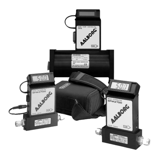
OPERATING MANUAL
GFM MASS
FLOW METERS
Quality System Registered
Table of
Contents
Previous
Page
Next
Page
1
2
3
4
5
Advertisement
Table of Contents
Troubleshooting
Adjust Scaling
18
Troubleshooting Guide
19
Need help?
Do you have a question about the GFM 17 and is the answer not in the manual?
Ask a question
Questions and answers
Related Manuals for Aalborg GFM 17
Measuring Instruments Aalborg GFM 67 Operating Manual
Gfm mass flow meters (32 pages)
Measuring Instruments Aalborg GFM 37 Operating Manual
Gfm mass flow meters (32 pages)
Measuring Instruments Aalborg XFM Series Operating Manual
Digital mass flow meters (56 pages)
Measuring Instruments Aalborg DPM Series Operating Manual
Intelligent digital mass flow meters (111 pages)
Measuring Instruments Aalborg DFM 26 Operating Manual
Digital mass flow meter (68 pages)
This manual is also suitable for:
Gfm 67
Gfm 57
Gfm 47
Gfm 37
Gfm 77
Table of Contents
Save PDF
Print
Rename the bookmark
Delete bookmark?
Delete from my manuals?
Login
Sign In
OR
Sign in with Facebook
Sign in with Google
Upload manual
Upload from disk
Upload from URL


Need help?
Do you have a question about the GFM 17 and is the answer not in the manual?
Questions and answers