
Related Manuals for powersoft Ottocanali HGT Series


Summary of Contents for powersoft Ottocanali HGT Series
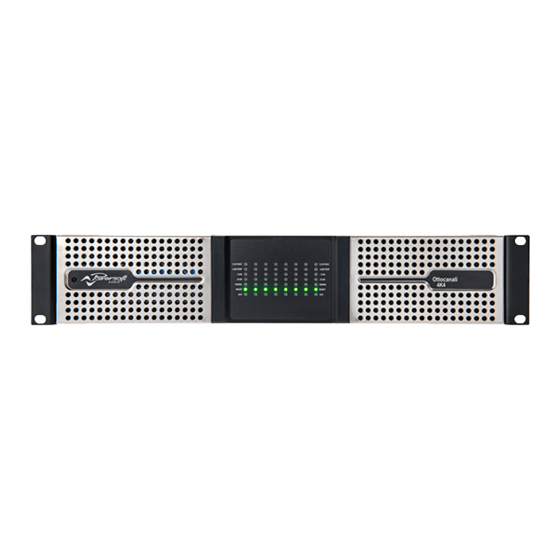
- Page 1 Ottocanali HGT Series Ottocanali Service Manual ©2017 Powersoft Keep this manual powersoft_OttocanaliHGT_servman_en_v2.7 for future reference...
- Page 2 Intentionally left blank...
-
Page 3: Table Of Contents
This technical document aims to be a support guide in repairing and 14. LOG files Extraction Procedure low-voltage testing the Ottocanali HGT series power amplifiers. 15. Checking the Digi Board for Faults The troubleshooting approach will help you characterize the kind of fault you incur. -
Page 4: Display Led Configurations And Further References
OTTOCANALI HGT | SERVICE MANUAL 1. Display LED Configurations and further references Over temperature Short circuit Power supply failures Power supply failures (per each channel) (per each channel) (per each module) (per each module) YELLOW YELLOW YELLOW YELLOW or BLINK GREEN GREEN GREEN... - Page 5 • The DSP parameters are installed, the green LEDs are on (2 seconds) • The amplifier is now ready for use. Different LEDs configurations could be symptoms of a malfunction, please follow the next steps: SD Card FW Recovery procedure Contact the Powersoft’s Service Centre...
-
Page 6: Opening The Amplifier's Cover
OTTOCANALI HGT | SERVICE MANUAL 2. Opening the amplifier’s cover Locate the 2 screws highlighted on (Fig. 1) and remove them by means of a PH1 Phillips head screwdriver. Fig. 1 Locate the 4 screws highlighted on (Fig. 2) and remove them by means of a PH2 Phillips head screwdriver. - Page 7 OTTOCANALI HGT | SERVICE MANUAL Accessing the AMP modules Locate and remove the 16 screws that secure the module’s covers, by means of a PH1 phillips head screwdriver. (Fig. 4) Fig. 4 Remove the fuses by gently pulling on the assembly. (Fig. 5) It is now possible to lift the module’s covers.
-
Page 8: Internal Led Statuses
OTTOCANALI HGT | SERVICE MANUAL 3. Internal LED Statuses 8CHHGT/STD/ANALOG LED Status In order to check the internal status LEDs, connect the amplifier to the mains, and switch it on. Refer to the following table for the LED configurations. COLOR STATUS ACTION -12V GREEN –12V green... -
Page 9: Disassembling The Digimod3004Pfc4 Modules
OTTOCANALI HGT | SERVICE MANUAL DigiMod 3004PFC4 Modules LED Status The LEDs disposition and their meanings are portrayed on (Fig. 6). Please refer to the DigiMod PFC4 Service manual for in depth repairing instructions. LED ID TYPE DESCRIPTION IDLE MODE SIGNAL MODE Status Auxiliary +12 V active... -
Page 10: Disassembling The 8Chhgt/Std/Analog
OTTOCANALI HGT | SERVICE MANUAL 5. Disassembling the 8CHHGT/STD/ANALOG By means of a PH1 Phillips Head screwdriver, remove the 3 screws that secure the 8CHHGT/STD/ANALOG board. 6. Disassembling the 8CHHGT/STD/DSPETH Start by unplugging all the connectors marked in Green, and Yellow. By gently pressing on the indicated points, extract the Brooklyn board. - Page 11 OTTOCANALI HGT | SERVICE MANUAL Gently pry the backside of the amplifier’s chassis open, as portrtrayed on (Fig. 7). Fig. 7 Carefully lift the DSPETH Board by pinching the heatsink as in (Fig. 8). Fig. 8...
-
Page 12: Disassembling The 8Chhgt/Std/Front
OTTOCANALI HGT | SERVICE MANUAL 7. Disassembling the 8CHHGT/STD/FRONT In order to disassble the front panel, remove both air filter covers as portrayed on (Fig. 9). These are held in place by a powerful magnet and no tool is required during this operation. Pro tip: dump the filters in a mild soap and water solution, then rinse them out and dry them thoroughly. -
Page 13: Disassembling The 8Chhgt/Std/Cntrl Board
OTTOCANALI HGT | SERVICE MANUAL 8. Disassembling the 8CHHGT/STD/CNTRL Board Fig. 13 Prior to removing the CNTRL Board it is necessary to remove the FRONT Board. Start by gently unplugging all the connectors highlighted in yellow on (Fig. 13). Proceed by unscrewing the screws and bolts highlighted in light blue on (Fig. -
Page 14: Disassembling The Fans
OTTOCANALI HGT | SERVICE MANUAL 9. Disassembling the Fans In order to disassemble the fans, unplug the fan’s connectors highlighted on (Fig. 15). Fig. 15 By means of a PH1 Phillips head screwdriver remove the screws that secure the fans to the chassis. (Fig. 16) Fig. -
Page 15: Output Connector Color Code
OTTOCANALI HGT | SERVICE MANUAL 10. Output connector colour code Use the following pictures and tables in order to plug all of the output connectors in the correct order. CH 1 - 4 CH 5 - 8 Channel Wire color Channel Wire color Channel... -
Page 16: Sd Card Fw Recovery Procedure
OTTOCANALI HGT | SERVICE MANUAL 11. SD Card FW Recovery Procedure Switch the unit off, let the capacitors discharge, and proceed by replacing the factory SD Card with the Recovery SD Card. Switch the Amplifier back on, and wait The amplifier will cycle all the steps involved in the power up sequence, and it should stop showing the LED configuration portrayed. -
Page 17: Usb Pen Drive Fw Update Procedure
13. USB Pen Drive FW Update Procedure All updates for the Ottocanali’s FW are stored within the Armonía Forum. Navigate to http://www.powersoft-audio.com/en/downloads/firmware Download the package, the name should appear as: update-v1.7.6.30-8ch.bin Extract the compressed file and place it in the USB Pen Drive. -
Page 18: Checking The Digi Board For Faults
OTTOCANALI HGT | SERVICE MANUAL 15. Checking the Digi Board for Faults This procedure involves checking the U61 and U27 regulators. 160 Ω Be extremely cautious and make sure that the internal capacitor’s bank is not charged. Start by checking, with a multimeter set to Ohm, the resistance between pin 1 and ground on the U61 regulator. - Page 19 OTTOCANALI HGT | SERVICE MANUAL Move to U27, and check the resistance between pin 7 and ground, as in (Fig. 20). 6 KΩ Fig. 20 Proceed by checking the resistance between pin 1 and ground, as in (Fig. 21). 900 KΩ Fig.
-
Page 20: Checking The Fans
OTTOCANALI HGT | SERVICE MANUAL Check the viability of the U27 regulator by probing between pin 1,7 and the chassis (ground). (Fig. 22) Pin 1 to ground: 12Vdc Pin 7 to ground: 5 Vdc Fig. 22 Check the viability of the U61 regulator by probing between pin 1,7 and the chassis (ground). -
Page 21: Spare Parts/Repair Kits List
OTTOCANALI HGT | SERVICE MANUAL 17. Spare Parts/Repair Kits List Part number Description VN000030 Fan wired 24Vdc 0.26A SM001040.R 8CHHGT/STD/DSPCNTRL SM000939 .R 8CHHGT/STD/ANALOG SM000938.R 8CHHGT/STD/RAILFUSE SM000933.R 8CHHGT/STD/CNTRL SM000906.R 8CHHGT/STD/DSPETH SM000884.R 8CHHGT/STD/ALARMREAR SM000883.R 8CHHGT/STD/INOUTREAR AC Mains cable (CV000061) SM000787.R 8CHHGT/STD/FRONT PF8CH296.R DIGIMOD 3004PFC4 PC000177 SD card... - Page 22 OTTOCANALI HGT | SERVICE MANUAL IMPORTANT SAFETY ADDENDUM The aim of this addendum is to describe the safety precautions to be undertaken when servicing any Powersoft amplifier/module. WE RECOMMEND THAT ALL SERVICE OPERATIONS ARE CARRIED OUT BY A TRAINED TECHNICIAN IF NOT EXPLICITLY STATED OTHERWISE, DISCONNECT THE AMPLIFIER FROM THE MAINS.
- Page 23 Intentionally left blank...
- Page 24 Tel: +39 055 735 0230 Fax: +39 055 735 6235 General inquiries: info@powersoft.it Sales: sales@powersoft.it Application & technical support: support@powersoft.it Service & maintenance: service@powersoft.it powersoft-audio.com Data are subject to change without notice. For latest update please refer to the online version available on www.powersoft-audio.com...
Need help?
Do you have a question about the Ottocanali HGT Series and is the answer not in the manual?
Questions and answers