Advertisement
Altronix SMP10PM is a supervised power supply that converts a low voltage AC input into 12VDC or 24VDC output
with a 10A continuous supply current.
Input:
• Input 24/28VAC.
(Voltage Output/Transformer Selection Table).
Output:
• 12VDC or 24VDC selectable output.
• 10A supply current.*
• Filtered and electronically regulated outputs.
• Short circuit and thermal overload protection.
Battery Backup:
• Built-in charger for sealed lead acid or gel type batteries.
• Maximum charge current 0.7A.
• Zero voltage drop when switching over to battery backup.
Output VDC
12VDC @ 10A
24VDC @ 6A
24VDC @ 10A
SMP10PM should be installed in accordance with The National Electrical Code and all applicable Local Regulations.
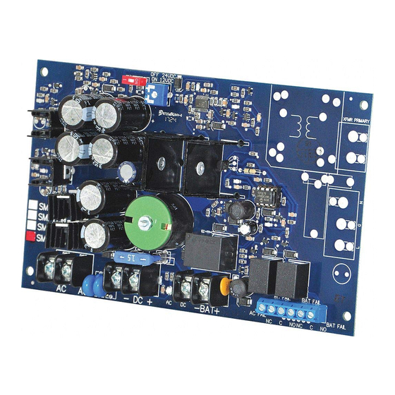
1. Mount the SMP10PM in the desired location/enclosure (mounting hardware included).
2. Set the SMP10PM to the desired DC output voltage by setting the switch (Fig. 1a, pg. 2) to the appropriate position
(Voltage Output/Transformer Selection Table).
Adjust output voltage by using the trimpot on the power supply board (Fig. 1a, pg. 2) prior to connecting devices.
3. Connect proper transformer to the terminals marked [AC] (refer to Voltage Output/Transformer Selection Table).
Use 18 AWG or larger for all power connections (Battery, DC output).
Keep power-limited wiring separate from non power-limited wiring (115VAC / 60Hz Input, Battery Wires).
Minimum 0.25" spacing must be provided.
CAUTION: Do not touch exposed metal parts. Shut branch circuit power before installing or servicing equipment.
There are no user serviceable parts inside. Refer installation and servicing to qualified service personnel.
4. Measure output voltage before connecting devices. This helps avoiding potential damage.
5. Connect devices to be powered to the terminals marked [– DC +].
6. When the use of stand-by batteries is desired, they must be lead acid or gel type. Connect battery to the terminals
marked [– BAT +] on the board (battery leads included). Use two (2) 12VDC batteries connected in series for
24VDC operation.
Note: When batteries are not used, a loss of AC will result in the loss of output voltage.
7. Connect appropriate trouble reporting devices to AC Fail and Low battery supervisory
relay outputs marked [NC, C, NO]. Use 22 AWG to 18 AWG for AC Fail / Low Battery reporting.
AC Failure will report in 5 minutes. For a 6 hour delay on reporting cut resistor R1.
Red (DC)
Green (AC)
ON
ON
ON
OFF
OFF
ON
OFF
OFF
SMP10PM
Supervised Power Supply/Charger
Specifications:
Voltage Output/Transformer Selection Table:
Switch Position
Transformer
SW1 - ON
24VAC or 28VAC / 175VA (Altronix model T2428175)
SW1 - OFF
24VAC or 28VAC / 175VA (Altronix model T2428175)
SW1 - OFF
24VAC or 28VAC / 300VA (Altronix model T2428300)
Installation Instructions:
LED Diagnostics:
Power Supply Status
Normal operating condition.
Loss of AC. Stand-by battery is supplying power.
No DC output.
Loss of AC. Discharged or no stand-by battery. No DC output.
Overview:
Supervision:
• AC fail supervision (form "C" contacts).
• Battery presence and low battery supervision
(form "C" contacts).
Indicators:
• AC input and DC output LED indicators.
Board Dimensions
7" x 4.25" x 1.25" (177.8mm x 107.9mm x 31.8mm).
* Specified at 25˚C ambient.
:
(W x L x H approximate)
Advertisement
Table of Contents

Related Manuals for Altronix SMP10PM


Summary of Contents for Altronix SMP10PM
- Page 1 SMP10PM should be installed in accordance with The National Electrical Code and all applicable Local Regulations. 1. Mount the SMP10PM in the desired location/enclosure (mounting hardware included). 2. Set the SMP10PM to the desired DC output voltage by setting the switch (Fig. 1a, pg. 2) to the appropriate position (Voltage Output/Transformer Selection Table).
- Page 2 OFF 24VDC ON 12VDC Altronix is not responsible for any typographical errors. Product specifications are subject to change without notice. 140 58th Street, Brooklyn, New York 11220 USA | phone: 718-567-8181 | fax: 718-567-9056 website: www.altronix.com | e-mail: info@altronix.com | Lifetime Warranty | Made in U.S.A.
Need help?
Do you have a question about the SMP10PM and is the answer not in the manual?
Questions and answers