Advertisement
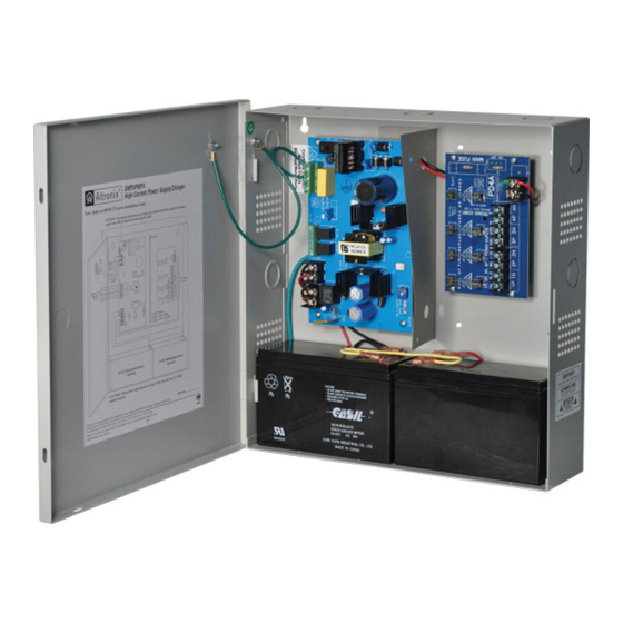
SMP5PM is a supervised power supply/charger that converts a low voltage AC input into a 12VDC or 24VDC se-
lectable output with 4A of continuous supply current (see specifications). This general purpose power supply has a
wide range of applications for access control, security and CCTV system accessories that require additional power.
Input:
• 24VAC or 28VAC
(See Voltage Output/Transformer Selection Table).
Output:
• 12VDC or 24VDC selectable output.
• 4A supply current.*
• Filtered and electronically regulated outputs.
• Short circuit and thermal overload protection.
Battery Backup:
• Built-in charger for sealed lead acid or
gel type batteries.
• Maximum charge current 0.3A.
* Specified at 25˚C ambient.
Output VDC
12VDC
24VDC
Note:
Transformers with higher VA ratings may be used for all output voltages above as long as you
do not exceed 28VAC or 45VDC.
SMP5PM should be installed in accordance with the National Electrical Code and all applicable Local Regula-
tions.
1. Mount SMP5PM board in the desired location/enclosure (mounting hardware included).
2. Set SMP5PM to the desired DC output voltage via SW1 (Voltage Output/Transformer Selection Table).
3. Connect proper transformer to the terminals marked [AC] (Voltage Output/Transformer Selection Table).
Use 18 AWG or larger for all power connections (Battery, DC output).
Use 22 AWG to 18 AWG for power-limited circuits (AC Fail/Low Battery reporting).
Keep power-limited wiring separate from non power-limited wiring (115VAC / 60Hz Input, Battery
Wires). Minimum 0.25" spacing must be provided.
CAUTION: Do not touch exposed metal parts.
Shut branch circuit power before installing or servicing equipment.
There are no user serviceable parts on board.
Refer installation and servicing to qualified service personnel.
4. Measure output voltage before connecting devices. This helps avoiding potential damage.
5. Connect devices to be powered to the terminals marked [+ DC –].
6. When the use of standby batteries is desired, they must be lead acid or gel type.
Connect battery to the terminals marked [+ BAT –] on the board (battery leads included).
Use two (2) 12VDC batteries connected in series for 24VDC operation.
Note: When batteries are not used, a loss of AC will result in the loss of output voltage.
7. Connect appropriate signaling notification devices to AC Fail & Low battery supervisory relay outputs marked
[NC, C, NO].
SMP5PM
Supervised Power Supply/Charger
Voltage Output/Transformer Selection Table:
Switch Position
Max. Load DC Transformer Requirements
SW1 ON
SW1 OFF
Installation Instructions:
Overview:
Specifications:
Battery Backup (cont'd):
• Zero voltage drop when switching over to
battery backup.
Supervision:
• AC fail supervision (form "C" contacts).
• Low battery supervision (form "C" contacts).
Visual Indicators:
• AC input and DC output LED indicators.
Board Dimensions (W x L x H approx.):
7" x 4.05" x 1.35" (177.8mm x 102.9mm x 34.3mm)
4A
24VAC or 28VAC / 100VA (T2428100)
4A
24VAC or 28VAC / 175VA (T2428175)
Advertisement
Table of Contents

Subscribe to Our Youtube Channel
Related Manuals for Altronix SMP5PM


Summary of Contents for Altronix SMP5PM
- Page 1 Supervised Power Supply/Charger Overview: SMP5PM is a supervised power supply/charger that converts a low voltage AC input into a 12VDC or 24VDC se- lectable output with 4A of continuous supply current (see specifications). This general purpose power supply has a wide range of applications for access control, security and CCTV system accessories that require additional power.
- Page 2 + BAT --- + DC --- Altronix is not responsible for any typographical errors. 140 58th Street, Brooklyn, New York 11220 USA | phone: 718-567-8181 | fax: 718-567-9056 website: www.altronix.com | e-mail: info@altronix.com | Lifetime Warranty | Made in U.S.A. MEMBER IISMP5PM - Rev. 090710...
Need help?
Do you have a question about the SMP5PM and is the answer not in the manual?
Questions and answers