
Related Manuals for SystemAir KA Series


Summary of Contents for SystemAir KA Series
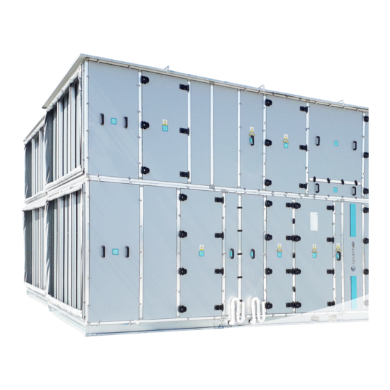
- Page 1 Modular air handling units Installation, operation and maintenance manual 2020-8-V-EN-003...
-
Page 2: Table Of Contents
Electric air heater ....................................53 3.7.8 Indirect gas heating coil ..................................54 Sound attenuator ..................................... 57 3.9 Humidifiers ........................................ 57 3.9.1 Steam humidifier ....................................57 3.9.2 Honeycomb humidifier ..................................58 3.9.3 High pressure humidifier ................................... 62 3.10 Electric control cabinet ................................... 63 REMOVAL AND DISPOSAL................................63 systemair... -
Page 3: General Information
GENERAL INFORMATION Information about manufacturer These instructions apply to all KA air handling units supplied by Systemair d.o.o., Slovenia. Service and technical support: Manufacturer and supplier details: Systemair d.o.o. Systemair d.o.o. Špelina ulica 2 Brnčičeva 41c 2000 Maribor 1000 LJUBLJANA Slovenija Slovenija Responsible person: Anton Zupančič... -
Page 4: General Description
Thermal transmittance factor Thermal bridge factor TB2 or TB3 Casing air leakage class (+700 Pa) Casing air leakage class (-400 Pa) Filter bypass leakage class Casing sound attenuation Casing with fully glued panels: 1000 2000 4000 8000 De dB systemair... -
Page 5: Declarations Regarding The Air Handling Unit
Caution The declaration of conformity or the declaration of incorporation shall be attached separately to each device. If the customer makes changes or adds components to the device, he must issue a new EC declaration of conformity and a new CE sign for the machine. Example of declaration of conformity Example of declaration of incorporation systemair... -
Page 6: Dangers And Warnings
Any other use deviating from the so-determined intended use relieves the manufacturer of any obligation or liability. • Systemair d.o.o, the manufacturer of the KA air handling unit, does not accept any liability in the event the directions indicated in these instructions are not adhered to while installing, commissioning, operating, testing or maintaining the air handling unit, or in the event of any alterations to the unit’s electrical or mechanical elements by any person... -
Page 7: Symbols
Filter section damper systemair... -
Page 8: Personnel Requirements, Assignments And Responsibilities
Must have in-depth knowledge and skills related to the required hardware systems. Must have experience with the work in question, understand the potential hazards associated with the work and how to avoid it. Network administrator Designs, installs, configures and maintains IT infrastructure in companies or organizations. systemair... -
Page 9: Operation And Control
The operating indications and error indications are displayed via the control system display and signal lights on the electric control cabinet, or on the separate hand-held terminal. As an alternative, the controller may be linked to a central monitoring system and new parameters can be set via a PC, tablet or smart phone. Operators do not need to open the service doors in order to operate the unit. systemair... - Page 10 • Prior to commissioning the unit, all the ducts must be installed and all the guards and protection devices must be in place to prevent access to the rotating parts of the fans. • D uring operation, all the service doors must be closed and locked. • D o not operate the unit without installing filters. • Do not operate the unit when external dampers are in closed position. systemair...
-
Page 11: Installation
A compact shipment unit of an air handling unit may only be hoisted with a crane applying a base frame or a transport pallet positioned under the unit. Appropriate hoisting beams with sufficient distance between the hoisting points should be used so as to prevent the hoisting slings from damaging the casing, the gutter or the handles, hinges, piping connections or other accessories (pressure gauges, pressure transducers, etc.) on the service side, or the electric control cabinet. systemair... - Page 12 Extra attention should be devoted to preventing such shipment units from tipping over. In the factory, such shipment units are protected so as to prevent the risk of their tipping over during transport and storage and endangering exposed persons. Caution High and short shipment units must be protected against tipping over. They may only be transported in the vertical position! systemair...
-
Page 13: Mounting
In the case of units that include a spray humidifier section, all the other sections should be mounted on a special steel base or provided an appropriate foundation. systemair... - Page 14 Mount the air handling unit on a foundation of adequate height. In determining the foundation height, observe all the factors that may affect the operation of the unit: the mounting site, the depth of snow cover, requirements for the intake air quality, the position of the intake and extract duct connections, the types of connectors for heat exchanger piping, the laying of electric cables, etc. systemair...
- Page 15 The platform must ensure safe climbing to and descending from the unit and safe maintenance. systemair...
-
Page 16: Assembly
This should always be the primary connection. Fastening material For each connection the following fastening material is always supplied: • 1x Screw DIN 933 Zn M8 x 70 • 1x Nut DIN 934 M8 Zn • 2x Washer DIN 9021 8,4 Zn systemair... - Page 17 • 1x Nut DIN 934 M8 Zn For each connection the following fastening material is always supplied: • 1x Screw DIN 933 Zn M8 x 70 • 1x Nut DIN 934 M8 Zn • 2x Washer DIN 9021 8,4 Zn systemair...
-
Page 18: Mounting Of Roof
• Fasten the roof to the unit with the supplied special self-tapping screws with a rubber washer. Fastening material For each connection the following fastening material is always supplied: • 1x Screw DIN 7504 K 410 HP 6,3 x 25 • 1x EPDM 22 systemair... -
Page 19: Connection Of Ducting
In the case of a centrifugal fan, the dimensions of the duct should be similar to those of the air outlet opening onto the fan, in order to avoid or minimise losses due to turbulence. In special cases, e.g. with vertical duct runs, buoyancy effects may induce an air flow that drives (rotates) a fan impeller even with the drive motor off. The rotating impeller poses a risk of injury during repair or maintenance works. This danger can be prevented by applying motor drives with counter-springs that automatically shut the dampers in the event of power supply failure. systemair... -
Page 20: Connection Of Piping
40/110 48 x 19 45/116 54 x 19 50/100 60 x 19 56/131 2 1/5 64 x 19 60/130 76 x 19 71/142 76 x 19 71/142 89 x 19 82/150 108 x 19 100/170 114 x 19 112/180 systemair... - Page 21 Caution Improper connection of hydraulic cyrcle can result in lower heat exchanger efficiency. The direction of the connections is mostly tied in the counterflow direction with respect to the direction of the air. The figure below shows the connections according to the medium: 1 – Water (heating and cooling) 2 – Freon (heating, cooling or combination) 3 – Steam (heating) Inlet Outlet systemair...
- Page 22 3 – balancing valve 4 – termometer 5 – termometer (optional) 6 – venting valve 7 – ball valve 8 – drain valve Caution 3-way valve for cooling hydraulic cyrcle can be mounted on the inlet or outlet. It is important to instal it with the required flow direction. systemair...
-
Page 23: Connection Of Siphons
(exit over base frame). Caution Vertical pipes must be cut in height according to the instructions below. Caution The 125 mm base frame is not sufficient to meet the required standard. A concrete base with a minimum height of 150 mm, additional feet, or a unit base frame with a height of 250 mm is required. systemair... - Page 24 Drain over bottom panel Drain over side panel depends on the maximum overpressure (Pa +) in the condensation section. Underpressure connection Drain over bottom panel Drain over side panel depends on the maximum underpressure (Pa -) in the condensation section. systemair...
- Page 25 Hmin > 60 mm. In the case of a underpressure, the height of the base of 125 mm corresponds to underpressure of 700 Pa, or H = 80 mm. A quick calculation of the siphon height with respect to underpressure or overpressure in the condensation section: Pa+ > P Pa- < P ΔP 1000 1200 systemair...
- Page 26 Drain over side panel is a minimum of 60 mm regardless of the overpressure in the device. Underpressure connection Caution Shows direction of the drainage flow in underpressure section. Drain over bottom panel Drain over side panel depends on the maximum underpressure (Pa -) in the condensation section. systemair...
-
Page 27: Connection Of Electrical Installation
Vibration and structure-borne noise Reduction of vibration transmission to the building is possible by connecting the device to the duct network via flexible connections and by placing the device on appropriate vibration isolators. To mitigate structural noise, we recommend using rubber or elastomeric pads under the device. To keep the unit properly aligned and working, carefully check the air conditioning alignment (opening and closing the door, connecting the modules). Caution We recommend that the anti-vibration pads, including the material and layout plan, are selected and determined through a professional company. systemair... -
Page 28: Commissioning And Maintenance
• C heck the gasket at the contact of the panel or door and casing. If the gasket is damaged or detached, it must be completely removed, the surface cleaned and gasket replaced. After maintenance • Clean any dirt from maintenance. • C heck that all mechanical and electrical components are in place and securely fastened. • M ake sure that no one is in the danger area of the device or its surroundings. • M ake sure you have removed all tools or other objects from the device. • C lose the service door and lock the handle locks. systemair... -
Page 29: Schedule For Control And Maintenance
Inspection of deposits of dirt and scale in the circulating pump suction connection Inspection of operation of the electrical conductivity measurement elements Inspection of operation of the sterilisation device. Inspection of oper. and cleanliness of the dirt traps Inspection of operation of the bleed-off device * if the bacteria count > 1000 CFU/ml , the water tank must be washed with cleaning agents, rinsed, dried and, if necessary, disinfected. systemair... -
Page 30: Fan
• Step 2: Connect the wires with staples in a star or delta connection. See the nameplate for more information. • Use a screened/armoured motor cable to comply with EMC emission specifications (or install the cable in metal conduit). • Keep the motor cable as short as possible to reduce the noise level and leakage currents. Caution All types of standard three-phase asynchronous motors can be connected to a frequency converter. systemair... - Page 31 Do not install cables with twisted ends. Such cables destroy the shielding effect at higher frequencies. If it is necessary to split the shield due to the installation of a motor insulator or motor relay, the shield must continue with the lowest possible high frequency impedance. systemair...
-
Page 32: Connection Of Ec Fan
5 Connection alarm relay 6 Connection contols +24V Power supply +24V +10V Power supply +10V Grounding Digital input (if we connect + 24V to D1 we activate the start condition) Analog input (0-10V) 7 Slot for add-on module Connection of EBM paps systemair... - Page 33 • the correct installation of the electrical connections and their operation (fuse sizes, contactors, thermal protection), • for the presence of any tools or other foreign materials in the section, • the mounting of all the covers and doors. • T hermal protection is essential for the safety of the electric motor, therefore, before starting the motor, check if it has the correct settings for the nominal current of the motor, and check its operation. Once this test has been successfully completed, seal the thermal protection device. systemair...
- Page 34 • The mounting of the rotor on the shaft, • the tightness of all the threaded joints, • the rotor run, • the vibration isolators of the fan-electric motor assembly, • t he flexible connections, and • t he shaft bearings; if axial shifts of shafts in the bearings are detected, consult the fan manufacturer and remedy the fault. systemair...
-
Page 35: Filter
M5 - F7 200 Pa or 3x starting pressure drop ePM1 60% F8 - F9 300 Pa ISO ePM1 100 Pa + starting pressure drop ePM1 75% E10 - H13 500 Pa ISO ePM2,5 or 3x starting pressure drop ePM1 85% ISO ePM10 systemair... -
Page 36: Bag Or Cassette Filter
• the accumulated hours of operation • t he visual appearance of filters (cracks in the filtering medium, leakage between the filters and the filter frame). Caution In the event of noticeable contamination, cracking in the filtering medium or leakage between the filters and the frame, replace the filters regardless of the current pressure drop or hours of operation. Time to replace filters: • w hen the allowable final pressure drop is achieved, • when the replacement interval has expired, • w hen the filter performance, in mechanical or hygienic terms, is no longer adequate, • i f the filters become contaminated following air handling unit installation or reconstruction, • if requested by the sanitary inspection. systemair... -
Page 37: Dirty Side Removable Cassette Filter
• r emove the wire springs / loosen the block profiles, • s lide out the bag filters, • clean the section casing if necessary, • inspect the condition of the sealing tape on the sealing contact surface and repair or replace the tape if necessary, • i nsert clean and undamaged filters. systemair... -
Page 38: Metal Filter
• clean the section casing if necessary, • i nsert clean filter cassettes, • c heck the connection of the pressure measuring hoses to the pressure measurement ports and connect the hoses if necessary. A soiled metal frame may be washed in hot water with cleaning agent added, observing the cleaning agent manufacturer’s instructions and ensuring the proper water temperature. Cleaned cells may be impregnated with BA or MA viscose, by means of soaking or spraying. systemair... -
Page 39: Active Charcoal Filter
• insert new cassettes in the opposite direction and in the reverse order, • c heck the air tightness of the filter frame-casing joints, • c heck the air tightness of the support plate-filter frame joints, • c heck the air tightness of the filter cassette-support plate joints. Under normal air ventilation conditions, relative humidity does not have a large effect on the adsorption capacity of activated carbon. systemair... -
Page 40: Absolute Filter
• r otate the filter cassette in the direction of the arrow and pry it out of the support plate, • r epeat the procedure to remove all the filter cassettes, • clean the section casing if necessary, • insert new cassettes in the opposite direction and in the reverse order, • c heck the air tightness of the filter frame-casing joints, • c heck the air tightness of the support plate-filter frame joints, • c heck the air tightness of the filter cassette-support plate joints. systemair... -
Page 41: Heat Recovery Units
• replace the cleaned inserts in the section in the reverse order of the mentioned steps. Caution Since the insert filler material is made of a very thin aluminium foil, be careful not to damage the front surfaces of the insert when disassembling. With any maintenance or inspection intervention, also clean the condensate discharge at the bottom of the pan and top up the water in the siphon. systemair... -
Page 42: Rotary Heat Exchanger
The honeycomb structure may be cleaned with compressed air, water, steam or special cleaning agents. Clean it manually or by means of the installed cleaning nozzles. Pressures of up to 150 bar can be applied. Caution The humidity transfer rotors may not be cleaned with water or steam. systemair... -
Page 43: Run Around Coil
(left) and a hydraulic circuit with controls (right). 1 Heating coil 2 Cooling coil 3 Condensat tray Maintenance (Hydraulic circle) • R egularly check the operation of the circulating pump and make sure to keep the piping between the heat exchangers properly vented. • T wice a year, check the operation of the control system. • A t the beginning of the winter season, check the anti-freezing capability of the medium and replace it if necessary. Replace the medium every two years. systemair... -
Page 44: Control Damper
Check the following: • the condition of the gears and blades, • the tightness of the threaded joints on ball joints and drive levers, • whether the damper blades open and close correctly and • w hether the motor drive is firmly mounted. systemair... -
Page 45: Heating And Cooling Coils
In order to absolutely prevent the risk of freezing, dry the tube bank by blowing it with compressed air after draining. If the automatic control of the air handling unit is supplied by Systemair, the anti-frost protection is integrated in the unit in the factory; if the control system is implemented by the customer or another installer, arrangements for heating coil anti-frost protection are obligatory. -
Page 46: Water Heating Coil
This applies even more so to the blades at the edge, since these are even more fragile. Caution Under no circumstances should you attempt to clean the blades with a hard object. systemair... -
Page 47: Water Cooling Coil
This applies even more so to the blades at the edge, since these are even more fragile. Caution Under no circumstances should you attempt to clean the blades with a hard object. systemair... -
Page 48: Direct Expansion (Dx)
• a solenoid valve (high-pressure – low-pressure limit), • an inspection glass, • a collector container, particulary in the cases of long pipes. Caution When planning the layout of piping, consider the oil recovery and other phenomena associated with Freon flow. systemair... - Page 49 • the correct volume of Freon (no droplets in the inspection glass), • t he dry condition of the unit (the inspection glass – colour indicator; dry – wet, in accordance with the manufacturer’s instructions), • the correct evaporation and condensation pressure. Upon commissioning, make sure that the electric heater in the sump sufficiently heats the Freon to evaporate any liquid fraction of Freon (either by keeping the heater on permanently even with the unit shut down or by turning it on in advance before the unit commissioning). Medium filling • Prior to filling the system, extract the air from it. Keep doing this until the piping system is dry and an adequate vacuum is achieved (see: filling of cooling systems). • T he system is usually filled through the suction connection on the compressor – larger compressors are fitted with a special connection. Upon releasing Freon from the cylinder into the system, start the compressor and keep filling until the specified evaporation pressure is reached and no more bubbles are seen in the inspection glass. systemair...
-
Page 50: Droplet Eliminator
(once a year), and clean or replace the eliminator if necessary. Be sure to install a properly sized siphon on the drain pipe to collect and drain the condensate. Instructions for the construction, installation and connection are given in section 2.3.5 – Connection of siphon. Correct air flow direction is illustrated in figure. systemair... -
Page 51: Steam Heating Coil
In order to avoid this, installation of an additional gravity condensate pump is recommended. With configurations featuring modulated steam preheaters, use of a gravity condensate pump is mandatory. • I n order to ensure smooth operation of the steam heating coil, make sure to supply it with dry saturated steam. Use of superheated steam results in decreased efficiency, while water droplets in wet steam damage pipe walls. The steam composition must meet the requirements of the applicable standards. Pay particular attention to the oxygen and carbon dioxide content, which may corrode and erode the heating coil tubes. Regularly check the steam quality in accordance with SIST EN 1861. systemair... - Page 52 In the event of high steam temperatures, arrangements must be provided to protect the fan electric motor from overheating during unit idling; this is achieved by automatically shutting off the supply of the heating medium into the heating coil and continued operation of the fan for a certain period of time (3 to 5 min) after the unit operation has stopped. systemair...
-
Page 53: Electric Air Heater
– above the electric heating elements, where the temperature reaches the highest levels in the event of air flow interruption. • The electric air heater is not waterproof, therefore, the electric air heater section must not be installed in a location exposed to water or water steam. systemair... -
Page 54: Indirect Gas Heating Coil
Audit door Safety thermostat and safety temperature limiter Gas burner with stepless control of heating power Pressure switch Thermal protection Shut-off ball valve Gas filter Gas pressure controller Gas pressure switch Magnetic valve for gas Throttle valve for gas Gas burner systemair... - Page 55 • All the electric cables, cable glands and protection tubes installed inside the casings of the left and right sections adjacent to the gas heating coil section must have insulation resistant to high temperatures. • F or the purposes of filtering air immediately upstream of the gas heating coil, apply a metal filter with no EPDM sealing tape and with no bottom pan (unless greases are to be filtered out). systemair...
- Page 56 70 °C, • t he operation of the safety thermostat (limiter), the function of which is to automatically stop and block the gas burner in the event the air temperature in the chamber surrounding the heat exchanger exceeds 90 °C, • t he sealing of the heat exchanger and the extraction of flue gases. systemair...
-
Page 57: Sound Attenuator
• The air handling unit control system must ensure that the relative humidity within the air handling system never exceeds 90%. • T he steam humidifier may only start operating after the air flow achieves appropriate velocity and temperature. • T he steam humidifier must stop operating even before the fan is stopped, or in the event of an interruption of the air flow due to an interruption in the operation of the air handling unit, in the event of relative humidity exceeding 90% or for any other reason. Maintenance Maintenance to be carried out according to the manufacturer’s instructions and maintenance schedule. systemair... -
Page 58: Honeycomb Humidifier
Droplet eliminator 10 Inspection window A Supply air B Moist air Water supply D Waste water drainage Water consumption Circulating water system: The total water consumption is the sum of the absorbed water (E) and the bleed-off water (O). Water bleed-off is necessary to maintain appropriate mineral and salt content levels in the humidifier section reservoir water. systemair... - Page 59 1000 - conversion factor ((g/min) to (l/min)) S = 1.41 + 0.42 = 1.83 l/min Commissioning • O n the humidified air outlet side, provide the humidifier section with a service space 300-300 mm in width. • Upon installation, seal all the gaps to the casing. • C onnect the water supply and drain from the humidifier with a siphon. Caution As regards microbiological parameters, the filling supply water must meet the requirements for potable water and the requirements of the applicable regulations. systemair...
- Page 60 • solenoid valve (not included in scope of standard equipment – only for direct water) • c onstant flow rate valve (only for direct water) The extraction of water: In order to facilitate water bleed-off from the humidifier section under negative pressure, an appropriate negative pressure siphon must be provided. Control: Star connection: 400 V / 3p /50 Hz Delta connection: 230 V / 1p /50 Hz Wiring diagram for 3-phase pump systemair...
- Page 61 • O = f0 x E, where: • E is the amount of absorbed water (l/min) • O is the amount of bleed-off water (l/min) • S et the bleed-off water flow rate by means of the bleed-off valve by turning the valve knob to the corresponding number (to the left or to the right), then check the bleed-off water flow rate (capture the bleed-off water in a container of a known capacity, not less than 1 litre, and measure the container filling time). Repeat this procedure until the correct bleed-off rate is achieved. systemair...
-
Page 62: High Pressure Humidifier
• Set the appropriate rate of the honeycomb humidifier bleed-off. To this end, carry out a chemical analysis of the supply water to obtain the necessary data, as follows: CaCO3 content (mg/l), Ca+ content (mg/l), HCO3- content (mg/l), pH value. From the water quality diagram (provided in the honeycomb humidifier manufacturer’s instructions), determine the bleed-off factor, f0. For a particular unit, calculate the bleed-off water volume according to the following formula: O = f x E, where: E is the amount of absorbed water (l/min) -
Page 63: 3.10 Electric Control Cabinet
An electric control cabinet on a separate pedestal next to the air handling unit The scope of supply from Systemair d.o.o. is the electric control cabinet itself, the wiring between the air handling unit and the electric control cabinet, and start-up, if so specified in the order confirmation. In such an arrangement, Systemair d.o.o. does not carry out the mounting of the electric control cabinet or any required construction works (penetrations, cable trays, laying of the power supply and control cables from the air handling unit to the electric control cabinet, etc.). - Page 64 Systemair d.o.o. Špelina ulica 2, SI-2000 Maribor, Slovenia Tel: +386 1 200 73 50 Fax: +386 1 423 33 46 info@systemair.si www.systemair.com...
Need help?
Do you have a question about the KA Series and is the answer not in the manual?
Questions and answers