
Related Manuals for ETI PI-800


Summary of Contents for ETI PI-800
- Page 1 PRIMARY INJECTION CIRCUIT BREAKER TEST SET INSTRUCTION MANUAL Models PI-800 and PI-1600 Electrical Test Instruments, LLC. 1301 Avondale Road, Suite J New Windsor, MD 21776 www.ETIPrecision.com (410) 857-1880 Fax (410) 857-1387...
-
Page 2: Table Of Contents
Electrical Test Instruments PI-800 and PI-1600 ============================================================================== TABLE OF CONTENTS SECTION I: GENERAL INFORMATION and SPECIFICATIONS WARNING Introduction General Description Monitor and Controller MAC-21 Proposed Enhancements Advantages Compared to Other Test Sets Trademarks MAC-21 Specifications PI-800 Specifications PI-1600 Specifications SECTION II: DETAILED DESCRIPTION... - Page 3 Electrical Test Instruments PI-800 and PI-1600 ============================================================================== Multi-pole Molded Case Breakers IV-8 Low Voltage Power Breakers IV-11 Motor Overload Relays IV-15 Ratioing Current Transformers IV-17 SECTION V: SERVICE INFORMATION AND DOCUMENTATION Maintenance and Calibration of PI-800/1600 Maintenance and Calibration of MAC-21...
-
Page 4: Section I: General Information And Specifications
Electrical Test Instruments PI-800 and PI-1600 Section I - General Information and Specifications ============================================================================== SECTION I GENERAL INFORMATION and SPECIFICATIONS WARNING WARNING READ THIS ENTIRE MANUAL THOROUGHLY FAMILIARIZE YOURSELF WITH THE UNIT OPERATION PRIOR TO CONNECTING THE UNIT TO A SOURCE OF POWER. -
Page 5: Introduction
============================================================================== INTRODUCTION A primary injection test set, such as the PI-800 and PI-1600, is a device with high current, low voltage AC outputs for testing direct acting low voltage circuit breakers. Current is injected through the main contacts of the breaker to simu-... - Page 6 The MAC-21 connects to the PI-800 by means of a single cable, which allows it to be placed in the interlocking ridges of the PI-Aux for a three-piece stacked unit. The out- puts are connected by means of two slotted bus bars, and four connection plates.
- Page 7 A convenient rotary switch selects the coarse tap. It activates relays in either the PI-800 or PI-Aux to provide 7 ranges of output for the PI-1600 combined unit. The indicator/control panel features: (1) An Input Voltage indicator, which lights whenever power is connected to...
-
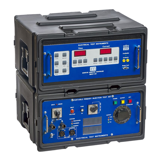
Page 8: Monitor And Controller Mac-21
Electrical Test Instruments PI-800 and PI-1600 Section I - General Information and Specifications ============================================================================== The MAC-21 is also capable of reading Peak RMS current, which can help detect waveform distortion on fast trips, as well as Last RMS current, which is useful for pickup tests. -
Page 9: Advantages Compared To Other Test Sets
The MAC-21 Monitor Ammeter Controller used in the PI-800 and PI-1600 has been used with great success in many retrofits of older test sets. It has been refined to be highly accurate, reliable, and easy to use. - Page 10 Electrical Test Instruments PI-800 and PI-1600 Section I - General Information and Specifications ============================================================================== SPECIFICATIONS MAC-21 Monitor Ammeter Controller CURRENT RANGES: 0-1000 A / 5 kA / 25 kA / 100 kA CURRENT ACCURACY: +/- 0.5% of reading + 0.5% Full Scale (Continu-...
- Page 11 Electrical Test Instruments PI-800 and PI-1600 Section I - General Information and Specifications ============================================================================== PI800 INPUT SUPPLY: 120 or 240 VAC + 10%, -15% (Switch Selectable), SINGLE PHASE 60 HZ (50 Hz at 10% lower maximum line voltages) 3.8 KVA (Continuous) at 3.4 KVA output (90% efficiency) PI-800 OUTPUT CURRENT &...
- Page 12 1 Minute 555 ** **Maximum output current possible into short circuit with very low source impedance Additional Equipment Required Requires a complete PI-800 (including MAC-21) for operation See separate data sheet for specifications DIMENSIONS AND NET WEIGHT (for PI-Aux Booster) Height: 11.5 in.
-
Page 13: Section Ii: Detailed Description
PI-800 Main Unit Circuitry Main power is applied to the PI-800 by means of standard high current plug and socket connectors, which are supplied for the customer to connect to the power source with appropriate flexible leads. - Page 14 Electrical Test Instruments MAC-21 Section III – MAC-21 ============================================================================== than about 160 VAC, this relay energizes to indicate connection to a voltage of 208 to 264 VAC. The Input Select Error indicator DS2 lights if it senses an incor- rect connection. The input voltage selector switch S1 sets the primary windings of transformer T4 in parallel in the 120 V position, and in series in the 240 V position.
-
Page 15: Pi-Aux Boost Unit Circuitry
Bus Overtemperature lamp DS13. PI-Aux Boost Unit Circuitry The PI-Aux Boost Unit connects to the PI-800 to form the PI-1600. SCR con- trolled voltage from the PI-800 is distributed to the four tap relays K1-K4, which provide power to the primaries of T1-T4 when energized. Output ON indicators DS1 and DS2 light when voltage is applied to the main input. - Page 16 Electrical Test Instruments MAC-21 Section III – MAC-21 ============================================================================== Interlock/Stop switch S4: This red switch turns off the main output of the test set by deenergizing contactor K1. Its lamp lights when there is an interlock con- dition. Output ON lamp DS5: This yellow lamp turns on when test set output is ON. Interlock Bypass Switch S5: This yellow switch, when held ON, bypasses the POD interlock.
- Page 17 Electrical Test Instruments MAC-21 Section III – MAC-21 ============================================================================== configuration. Voltage may be present on this connector anytime the interlock contactor is closed. A safety cover or other means should be used to prevent inadvertent contact with energized conductors when the PI-AUX unit is not connected.
- Page 18 Electrical Test Instruments MAC-21 Section III – MAC-21 ============================================================================== MEMORY AMMETER CONTROLLER MAC-21 INSTRUCTION MANUAL Firmware Version 3.06 and above Electrical Test Instruments, LLC 1301 Avondale Road, Suite J New Windsor, MD 21776 www.ETIPrecision.com (410) 857-1880 Fax (410) 857-1387 ============================================================================== Copyright(C) 1994-2004 Electrical Test Instruments, LLC All Rights Reserved...
-
Page 19: Mac-21 Specifications Iii-1
Electrical Test Instruments MAC-21 Section III – MAC-21 ============================================================================== MAC-21 Specifications INPUT POWER: 120 VAC, SINGLE PHASE 50/60 HZ, 20 VA Max CURRENT RANGES: 0-1,000 / 5,000 / 25,000 / 100,000 Amperes CURRENT ACCURACY: +/- 0.5% Reading + 0.5% Range + 1 Digit (Continuous) +/- 1.0% Reading + 1.0% Range + 1 Digit (Pulse >... - Page 20 Electrical Test Instruments MAC-21 Section III – MAC-21 ============================================================================== MAJOR PARTS IDENTIFICATION AND OPERATION MAC-21 Control Panel TIME DISPLAY: This 4-digit LED display normally indicates the elapsed time of a cur- rent pulse. In SECONDS mode, it displays time up to 9.999 seconds, then auto ranges to 99.99 seconds, 999.9 seconds, and 9999 seconds.
- Page 21 Electrical Test Instruments MAC-21 Section III – MAC-21 ============================================================================== takes the unit out of PRESET ADJUST mode. MAINTAIN key: This key toggle the MAINTAIN mode for initiation; its LED indicates that this mode is enabled. When in MAINTAIN mode, the INITIATE key need only be pressed briefly to turn output on.
- Page 22 Electrical Test Instruments MAC-21 Section III – MAC-21 ============================================================================== SECONDS key: This key normally selects the SECONDS time base. If the PRESET mode is selected, this key is used to LOWER the preset time limit by decrements of 1.000 second (5.000 seconds above 10.00) with the SECONDS time base, or 1.0 cycles with the CYCLES time base.
- Page 23 Electrical Test Instruments MAC-21 Section III – MAC-21 ============================================================================== remote initiate function (see below). A resistance of about 200 ohms or less will be in- terpreted as continuity. Although the signal is low power and transformer isolated, it is good practice to avoid touching any conductive surface connected to these termi- nals.
-
Page 24: Mac-21 Internal Parts Iii-8
Electrical Test Instruments MAC-21 Section III – MAC-21 ============================================================================== MAC-21 Internal Parts INPUT CONNECTOR: This connector, located on the upper rear corner of the MAC-21, provides 120 VAC control power, and connects to the air core CT (current sensor), and initiate circuitry of the test set. -
Page 25: Maintenance And Calibration Of Mac-21
Electrical Test Instruments MAC-21 Section III – MAC-21 ============================================================================== SERVICE INFORMATION AND DOCUMENTATION MAINTENANCE AND CALIBRATION OF THE MAC-21 The MAC-21 is manufactured using solid state components that should not re- quire extensive maintenance. However, the accuracy of the MAC-21 is critical to the testing of circuit breakers and is dependent upon the output of an air-core current sensing coil, which could change due to movement caused by shock or vibration encountered in transporting the test set. - Page 26 Electrical Test Instruments MAC-21 Section III – MAC-21 ============================================================================== important, because waveform distortion is more prevalent at lower levels. 7. If the MAC-21 reading differs from the standard by more than rated accu- racy, adjust the gain potentiometer on the analog board for proper read- ing.
- Page 27 Electrical Test Instruments MAC-21 Section III – MAC-21 ============================================================================== PARTS LIST (MAC-21): The overall schematic is on the following pages. The parts list is provided below. Please refer to both when ordering replacement parts. ITEM QTY DESCRIPTION Part Number 1 MAC-21 Contact/LED Harness S-B369 1 MAC-21 Rear Panel Harness S-B368...
- Page 28 Electrical Test Instruments MAC-21 Retrofit Package Section III – MAC-21 =============================================================================================================== Connections (MAC-21): ============================================================================================================= Copyright(C) 1994-2003 Electrical Test Instruments, LLC All Rights Reserved...
- Page 29 Electrical Test Instruments PI-800 and PI-1600 Section II - Detailed Description ============================================================================== ============================================================================== Copyright(C) 1994-2003 Electrical Test Instruments, Inc. All Rights Reserved...
-
Page 30: Section Iv: Operating Instructions
4. Calculate KVA requirements for the source per manufacturer’s manual. Remove lids from front and rear of all units. For PI-1600, place PI-800 on top of PI-AUX Boost Unit, plug power and control cables into jacks on PI-800. Connect inner output terminals with M-D175 connection bars per diagram. - Page 31 ============================================================================== 8. Important! Set output mode switch to proper position. See diagram. Connect the PI-800 to a good earth ground with at least #10 AWG wire. 10. Place MAC-21 on top of PI-800 and connect to jack on rear. 11. If possible, TURN OFF power at source.
- Page 32 Electrical Test Instruments PI-800 and PI-1600 Section IV - Operating Instructions ============================================================================== 20 V @ 400 A 5 V @ 1600 A 10 V @ 800 A Output Low Output High 1 (GND) 1 (GND) 1 (GND) 400 A M-D166...
-
Page 33: Basic Guidelines And Suggestions
Electrical Test Instruments PI-800 and PI-1600 Section IV - Operating Instructions ============================================================================== BASIC GUIDELINES AND SUGGESTIONS 1. Best timing and current accuracy will be obtained with the MAC-21 in cur- rent latch (C.L.) mode. 2. Current Latch modes are preferred for most testing purposes. Exceptions... - Page 34 Electrical Test Instruments PI-800 and PI-1600 Section IV - Operating Instructions ============================================================================== used for testing can usually be used at a 50% duty cycle, which allows 1.414 times the true continuous current for a maximum of 15 to 30 minutes, followed by an equal amount of time for cooling.
-
Page 35: Single Pole Molded Case Breakers
Electrical Test Instruments PI-800 and PI-1600 Section IV - Operating Instructions ============================================================================== allow mostly unrestricted testing in all but the most demanding situations, and then will indicate when it is safe to proceed without worrying about an overload trip or test set damage. - Page 36 Electrical Test Instruments PI-800 and PI-1600 Section IV - Operating Instructions ============================================================================== correct value by using vernier control, or press MAINTAIN key for current hold. 15. When breaker trips, the test set output should de-energize, timer should stop, and OUTPUT ON light should turn off.
-
Page 37: Multi-Pole Molded Case Breakers
Electrical Test Instruments PI-800 and PI-1600 Section IV - Operating Instructions ============================================================================== breaker. 13. Shut down test set, disconnect breaker, and prepare for subsequent test- ing or relocation according to steps 19 through 23 in pre-test installation and setup outlined above. - Page 38 Electrical Test Instruments PI-800 and PI-1600 Section IV - Operating Instructions ============================================================================== insufficient current is obtained at maximum position of the vernier, set the OUTPUT TAP control to the next higher tap, return the vernier to zero, and continue. 11. Press RESET button.
- Page 39 Electrical Test Instruments PI-800 and PI-1600 Section IV - Operating Instructions ============================================================================== 7. Press PRESET again to return to normal mode. 8. Select MEMORY mode. 9. Repeatedly jog the INITIATE button, while adjusting the OUTPUT CONTROL higher, until the circuit breaker trips instantaneously. This is the approximate pickup point.
-
Page 40: Low Voltage Power Breakers
Electrical Test Instruments PI-800 and PI-1600 Section IV - Operating Instructions ============================================================================== LOW VOLTAGE POWER CIRCUIT BREAKERS Nearly all low voltage power circuit breakers are multi-pole devices. The trip units may be either magnetic with a dash pot or solid-state electronic devices. - Page 41 Electrical Test Instruments PI-800 and PI-1600 Section IV - Operating Instructions ============================================================================== Consult breaker manufacturer's literature to determine any necessary pre- cautions and expected test results. A test current of three times the rating of the breaker should be used for this test.
- Page 42 Electrical Test Instruments PI-800 and PI-1600 Section IV - Operating Instructions ============================================================================== 20. Shut down test set, disconnect breaker, and prepare for subsequent test- ing or relocation according to steps 19 through 23 in pre-test installation and setup outlined above.
- Page 43 Electrical Test Instruments PI-800 and PI-1600 Section IV - Operating Instructions ============================================================================== testing or relocation according to steps 19 through 23 in pre-test installa- tion and setup outlined above. Pick-Up of the Instantaneous Unit Consult breaker manufacturer's literature to determine any necessary pre- cautions and expected test results.
-
Page 44: Motor Overload Relays
Electrical Test Instruments PI-800 and PI-1600 Section IV - Operating Instructions ============================================================================== Instantaneous Trip Time Test Perform Instantaneous Pickup Test as outlined above. Adjust controls to obtain current above pickup, at approximate desired multiple of rating. Close breaker under test. - Page 45 Electrical Test Instruments PI-800 and PI-1600 Section IV - Operating Instructions ============================================================================== 5. Set TIMEBASE to CYCLES. 6. Press PRESET key. Adjust preset time to 5.0 cycles. This value may be set higher or lower, depending on trip characteristics of breaker.
-
Page 46: Ratioing Current Transformers
Electrical Test Instruments PI-800 and PI-1600 Section IV - Operating Instructions ============================================================================== RATIOING CURRENT TRANSFORMERS To conduct a ratio test on a current transformer, a good multi-range bench ammeter is required in addition to the breaker test set. The breaker test set supplies primary current to the transformer and the bench ammeter is used to read the transformer secondary current. -
Page 47: Section V: Service Information And Documentation
Vernier brushes should be inspected for signs of wear or overheating, and cleaned or replaced as required. Calibration of the PI-800 and PI-1600 requires accurate current measurement in both series and parallel connection. Adjustment may be accomplished by means of the potentiometers accessible through the chassis when the rear panel is removed. - Page 48 Electrical Test Instruments PI-800 and PI-1600 Section V – Service Information and Documentation ============================================================================== Therefore, proper operation and calibration should be checked at regular inter- vals, and adjusted if proper equipment is available. The manufacturer’s recom- mended calibration interval is (1) one year.
- Page 49 Electrical Test Instruments PI-800 and PI-1600 Section V – Service Information and Documentation ============================================================================== 11. Set the current at 50% of full scale (500 A), and stop the current. 12. Set the MAC-21 to MEMORY mode, and press the RESET Switch.
- Page 50 Electrical Test Instruments PI-800 and PI-1600 Section V – Service Information and Documentation ============================================================================== PARTS LIST (PI-800): The overall schematic is at the end of the manual. The parts list is provided below. Please refer to both when ordering replacement parts.
-
Page 51: Parts List (Pi-Aux
Electrical Test Instruments PI-800 and PI-1600 Section V – Service Information and Documentation ============================================================================== PARTS LIST (PI-AUX): The overall schematic is at the end of the manual. The parts list is provided below. Please refer to both when ordering replacement parts. - Page 52 Electrical Test Instruments PI-800 and PI-1600 Section V – Service Information and Documentation ================================================================================= ================================================================================= Copyright(C) 1994-2003 Electrical Test Instruments, LLC. All Rights Reserved...
- Page 53 Electrical Test Instruments PI-800 and PI-1600 Section V – Service Information and Documentation ============================================================================== ============================================================================== Copyright(C) 1994-2003 Electrical Test Instruments, LLC. All Rights Reserved Page V-7...
- Page 54 Electrical Test Instruments PI-800 and PI-1600 Section V – Service Information and Documentation ============================================================================== ============================================================================== Copyright(C) 1994-2003 Electrical Test Instruments, LLC. All Rights Reserved Page V-8...
- Page 55 Electrical Test Instruments PI-800 and PI-1600 Section V – Service Information and Documentation ============================================================================== PI-800 Output Connections 4.5 Volt 800 Amp ============================================================================== Copyright(C) 1994-2003 Electrical Test Instruments, LLC. All Rights Reserved Page V-9...
- Page 56 Electrical Test Instruments PI-800 and PI-1600 Section V – Service Information and Documentation ============================================================================== PI-800 Output Connections 9 Volt 400Amp ============================================================================== Copyright(C) 1994-2003 Electrical Test Instruments, LLC. All Rights Reserved Page V-10...
- Page 57 Electrical Test Instruments PI-800 and PI-1600 Section V – Service Information and Documentation ============================================================================== PI-1600 Output Connections 10 Volt 800Amp ============================================================================== Copyright(C) 1994-2003 Electrical Test Instruments, LLC. All Rights Reserved Page V-11...
- Page 58 Electrical Test Instruments PI-800 and PI-1600 Section V – Service Information and Documentation ============================================================================== PI-1600 Output Connections 5 Volt 1600Amp ============================================================================== Copyright(C) 1994-2003 Electrical Test Instruments, LLC. All Rights Reserved Page V-12...
-
Page 59: Warranty
Retrofit Package Electrical Test Instruments PI-800 and PI-1600 Electrical Test Instruments Section V – Service Information and Documentation Section V - Service Information and Documentation ============================================================================== ================================================================================ WARRANTY Electrical Test Instruments, LLC, will correct any defect in workmanship or material for two years after date of purchase of any Electrical Test Instruments product.
Need help?
Do you have a question about the PI-800 and is the answer not in the manual?
Questions and answers