Table of Contents
Advertisement
Quick Links
Advertisement
Table of Contents

Related Manuals for ETI IR-500


Summary of Contents for ETI IR-500
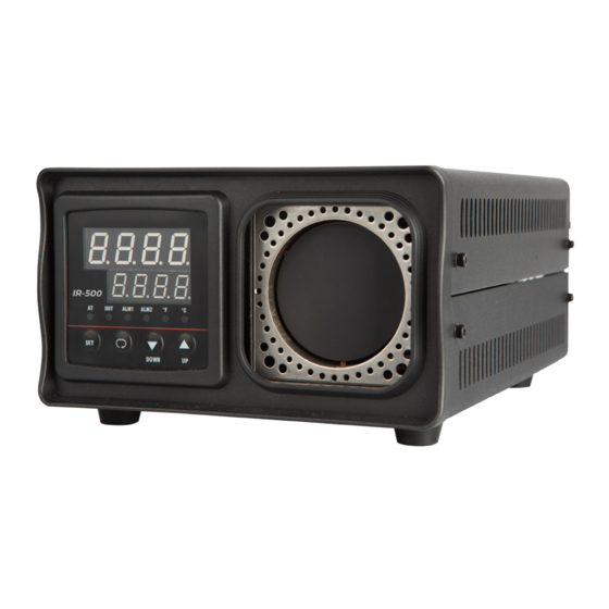
- Page 1 IR-500 BLACK BODY CALIBRATOR User Manual Product Code 822-400...
-
Page 3: Safety Information
SAFETY INFORMATION Use this instrument only as specified in this manual, otherwise, the protection provided by the instrument may be impaired. Please note the warnings and cautions listed below. WARNINGS BURN HAZARD- DO NOT touch the IR target surface of the unit. The temperature of the IR target surface is the same as the actual temperature shown on the display. - Page 4 INTRODUCTION The IR-500 Calibrator is mainly structured by 58 mm diameter target assembly and dry-well temperature system controlled by a microcomputer. The external reference thermometer is a metal cone with good heat-conducting ability, on the surface of thermometer there is a oxide film with emissivity 0.95.
-
Page 5: Environmental Conditions
ENVIRONMENTAL CONDITIONS Although the instrument has been designed for optimum durability and trouble-free operation, it must be handled with care. The instrument should not be operated in an excessively dusty or dirty environment. Maintenance and cleaning recommendations can be found in the Maintenance section of this manual. -
Page 6: Quick Start
QUICK START UNPACKING Unpack the calibrator carefully and inspect it for any damage that may have occurred during shipment. If there is shipping damage notify ETI Ltd immediately. Verify that the following components are present: • Calibrator • Power Cord •... -
Page 7: Parts And Controls
PARTS AND CONTROLS The user should become familiar with the calibrator and its parts. BACK PANEL Fig 1. Back Panel Description The back panel (Figure 1) consists of the power cord inlet, power switch, heater voltage switch, and fan. Wind input 2 Fuse of heater 3 Fuse of temperature control system 4 Power Input... -
Page 8: Controller Keypad
FRONT PANEL The front panel(Figure 2) consists of the controller display, controller keypad. and target assembly. Fig 2. Front Panel Description Controller Display 1 The red LED (the first line display) displays actual temperatures and settings for selected scale °C or °F. 2 The green LED (the second line) displays the set-point value and shows temperatures in units according to selected scale °C or °F. -
Page 9: General Operation
GENERAL OPERATION Place the calibrator on a flat surface with at least 8 inches of free space around the instrument, with the instrument facing the user. • Connect the calibrator to the power supply, ensuring correct voltage (11OV or 220V). •... -
Page 10: Controller Operation
CONTROLLER OPERATION This section shows you in detail how to operate the instrument temperature controller using the front control panel. Using the front panel key-switches and LED display the user may monitor the well temperature, the heater output power and adjust the controller proportional band. The control buttons (SET, DOWN, UP) are used to set the calibrator temperature set-point. - Page 12 Supplied by Electronic Temperature Instruments Ltd Easting Close, Worthing, West Sussex BN14 8HQ 01903 202151 · sales@etiltd.com · etiltd.com 822-400/24.11.20...
Need help?
Do you have a question about the IR-500 and is the answer not in the manual?
Questions and answers