Table of Contents
Advertisement
http://www.generac.com/service-support/product-support-lookup
Para español, visita:
Pour le français, visiter:
SAVE THIS MANUAL FOR FUTURE REFERENCE
Installation Manual
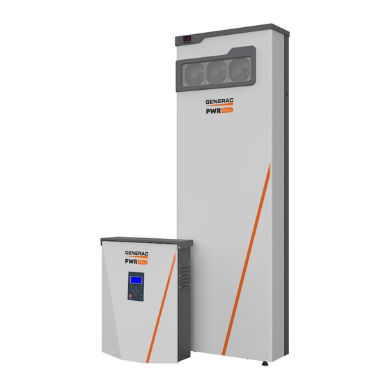
Generac PWRcell™ Battery
Loss of life. This product is not intended to
be used in a critical life support application.
Failure to adhere to this warning could result
in death or serious injury.
Register your Generac product at:
https://pwrfleet.generac.com
Register your Generac product at:
WWW.GENERAC.COM
http://www.generac.com/service-support/product-support-lookup
ON
OFF
WARNING
1-888-GENERAC
(888-436-3722)
1-888-GENERAC
(1-888-436-3722)
008980
(000209b)
Advertisement
Table of Contents

Subscribe to Our Youtube Channel
Related Manuals for Generac Power Systems PWRcell Series


Summary of Contents for Generac Power Systems PWRcell Series
- Page 1 Installation Manual Generac PWRcell™ Battery 008980 WARNING Loss of life. This product is not intended to be used in a critical life support application. Failure to adhere to this warning could result in death or serious injury. (000209b) Register your Generac product at: https://pwrfleet.generac.com 1-888-GENERAC (888-436-3722)
- Page 2 Use this page to record important information about your Generac Product Record the information found on your unit data label on this Operation and Maintenance: Proper maintenance and care of Serial Number Locations the energy storage system ensures a minimum number of page.
-
Page 3: Table Of Contents
Table of Contents Section 1: Safety Rules & General Connecting Blackstart Battery ........16 Information Installing Battery Modules ........ 16 Installing Rear Modules ..........17 Introduction ............1 Installing Grounding Tabs .........17 Read This Manual Thoroughly ........1 Installing Front Modules ..........17 Safety Rules ............1 Installing Module Spacer (PWRcell 9 and How to Obtain Service ..........1 PWRcell 15 only) ............18... - Page 4 This page intentionally left blank. Installation Manual for Generac PWRcell Battery...
-
Page 5: Section 1: Safety Rules & General Information
Safety Rules & General Information Section 1: Safety Rules & General Information Introduction This installation manual provides instructions and not all-inclusive. If using a procedure, work method, or recommendations for installing and commissioning the operating technique that the manufacturer does not spe- Generac PWRcell™... -
Page 6: General Hazards
Safety Rules & General Information General Hazards • Connecting the PWRcell system to the electric util- DANGER ity grid must only be done after receiving prior approval from the utility company. Loss of life. Property damage. Installation must • Only competent, qualified personnel should install, always comply with applicable codes, standards, laws operate, and service this equipment. -
Page 7: Electrical Hazards
Safety Rules & General Information Electrical Hazards DANGER WARNING Electrocution. Never connect this unit to the electrical Electrocution. Refer to local codes and standards for safety equipment required when working with a live system of any building unless a licensed electrician electrical system. -
Page 8: Battery Hazards
Safety Rules & General Information Battery Hazards General Rules DANGER WARNING Explosion. Do not dispose of batteries in a fire. Loss of life. Property damage. Installation must always Batteries are explosive. Electrolyte solution can cause comply with applicable codes, standards, laws and burns and blindness. -
Page 9: Standards Index
Safety Rules & General Information Standards Index WARNING Loss of life. This product is not intended to be used in a critical life support application. Failure to adhere to this warning could result in death or serious injury. (000209b) Strictly comply with all applicable national, state, and local laws, as well as codes or regulations pertaining to the installation of the system. - Page 10 Safety Rules & General Information This page intentionally left blank. Installation Manual for Generac PWRcell Battery...
-
Page 11: Section 2: General Information
General Information Section 2: General Information Specifications Description Units PWRcell 9 PWRcell 12 PWRcell 15 PWRcell 17 Energy Usable Energy 11.4 14.3 17.1 Power Continuous 60 minutes 10.0 2 minutes Battery Modules Number DC Voltage (per module) 46.8 (39-52) REbus Communication Protocol REbus DC nanogrid 360-420... -
Page 12: Serial Number Locations
General Information Serial Number Locations Unit Dimensions Refer to Figure 2-1 to locate serial numbers for the unit (A) and the individual battery modules (B). Record this information in Table 1: Important Information on the inside front cover of this manual so it is available if the tags are lost or damaged. -
Page 13: About Pwrcell Battery
General Information About PWRcell Battery The PWRcell battery is the storage component of the Figure 2-3, a REbus-compatible PWRcell Inverter (E) PWRcell system. The battery can be used for grid- is directly connected to PV Link (B) and PWRcell battery connected solar applications such as self-supply, rate (C) on the DC (REbus) line (D). -
Page 14: Component Locations
General Information Component Locations Battery Disconnect Switch DANGER Electrocution. Initiate a system-wide shutdown and turn the PWRcell Disconnect Switch OFF on all connected batteries before performing service. Failure to do so will result in death, serious injury, equipment and property damage. -
Page 15: Section 3: Location And Compliance
Location and Compliance Section 3: Location and Compliance Location and Clearances Install the PWRcell battery in dwelling units in the follow- • Interconnected smoke alarms must be installed ing permitted locations only: throughout the dwelling unit, including rooms, attached garages, and areas in which the battery is •... -
Page 16: Compliance
Location and Compliance Compliance Note on DC Wiring and the NEC Some electricians or installers may be unfamiliar with DC DANGER wiring in a residential setting. Note the following: Loss of life. Property damage. Installation must • NEC 215.12(C)(2) for correct DC wiring coloring. always comply with applicable codes, standards, laws •... -
Page 17: Section 4: Installing Generac Pwrcell Battery
Installing Generac PWRcell Battery Section 4: Installing Generac PWRcell Battery Carton Contents Installing Battery Cabinet • Wall bracket WARNING • Chassis (gray), including pre-installed electronics Personal Injury. Use caution when handling heavy parts and package and battery jumpers battery modules. Lift heavy parts in teams if necessary. Failure •... -
Page 18: Battery Dimensions And Knockout Locations
Installing Generac PWRcell Battery Battery Dimensions and Knockout Locations 9-7/8 in (25.1 cm) 22-3/16 in (56.3 cm) 1-5/16 in (3.3 cm) 13-3/8 in (34 cm) 57-5/8 in 9-3/8 in (146.3 cm) (23.9 cm) 1-1/4 in (3.12 cm) 42-13/16 in 41-5/8 in (108.7 cm) (105.7 cm) 67-5/8 in... -
Page 19: Placing Body Onto Bracket And Leveling Feet
Installing Generac PWRcell Battery Placing Body onto Bracket and Leveling Feet Figure 4-2. Lift body (A) onto bracket (B). Verify there is minimum 1-3/4 in (4.45 cm) gap Keep body tight to the wall while lowering body between the bottom of the body and the floor. onto bracket. -
Page 20: Connecting Blackstart Battery
Installing Generac PWRcell Battery Connecting Blackstart Battery To install REbus wiring: Figure 4-4. Install REbus conductors to their Figure 4-5. Connect blackstart battery lead to bat- terminal blocks: RE+ to red (A), RE- to blue (B). tery terminal (E). Install equipment grounding conductor to green ter- NOTE: One lead is already connected to terminal (F). -
Page 21: Installing Rear Modules
Installing Generac PWRcell Battery Installing Rear Modules Figure 4-9. Install grounding tabs (L) at the top of the module on both sides. Figure 4-7. Angle top of battery module (G) Fasten each grounding tab with a M4x8 mm SEMS under and behind bracket lip (H). screw (M) and torque to 13 in-lb (1.47 Nm). -
Page 22: Installing Module Spacer (Pwrcell 9 And Pwrcell 15 Only)
Installing Generac PWRcell Battery Installing Module Spacer (PWRcell 9 and PWRcell 15 only) Figure 4-11. Module spacers (O) must be installed on any single module shelf. 009935 Figure 4-13. Installing Module Spacer (2 of 3) Figure 4-14. Secure spacer with two M4X8 SEMS screws and torque to 13 in-lb (1.47 Nm). -
Page 23: Connecting Com Cables
Installing Generac PWRcell Battery Figure 4-16. Note that there are three types of Secure retention clip to bracket with a M4X8 mm retainer clips: double retention clips (U), single retention screw and torque to 13 in-lb (1.47 Nm). clips marked O (T) and single retention clips marked X Connecting COM Cables (S). -
Page 24: Connecting Battery Power Cable
Installing Generac PWRcell Battery Figure 4-19. Continue connecting the remain- ing battery modules. While installing CAT5 cables: • Work from top to bottom • Connect battery modules sharing a shelf with a black jumper cable (I) going from the rear battery COM OUT port to the front battery COM IN port •... -
Page 25: Installing Cover
Installing Generac PWRcell Battery Installing Cover Upgrading PWRcell Battery Figure 4-23. Place cover (A) upright in front of Figure 4-23. Inside of the PWRcell battery, battery unit. modules are stacked 2-deep on three levels, allowing for up to 6 modules to be connected in a series. In systems Slide cover straight back until it engages with body with less than 6 modules, a PWRcell battery can be (B). -
Page 26: Maximizing Battery Capacity After Upgrade
Installing Generac PWRcell Battery Enable the PWRcell inverter. Add the new modules into the string. – Navigate to the inverter device page. – Connect power and communications cables in the appropriate sequence. – Select Enable. – See Installing Battery Modules for more infor- –... -
Page 27: Section 5: Commissioning
Commissioning Section 5: Commissioning General Information Configure Battery 1. Select Mod. Settings on the PWRcell inverter con- NOTE: Register the PWRcell inverter are commissioning trol panel. at https://pwrfleet.generac.com. 2. Configure Mod. Settings setpoints as desired. See Before commissioning PWRcell battery verify all wiring is the Generac PWRcell Battery Owner’s Manual. -
Page 28: Decommissioning
Commissioning Decommissioning Decommissioning Plan WARNING The owner of the PWRcell battery system and the Environmental Hazard. Always recycle batteries at an qualified Generac Service Dealer shall prepare a written official recycling center in accordance with all local decommissioning plan that provides the overview of the laws and regulations. -
Page 29: Section 6: Troubleshooting
Troubleshooting Section 6: Troubleshooting General Troubleshooting Some of the more common problems are listed in the table below. This information is intended to be a check or verification that simple causes can be located and fixed. It does not cover all types of problems. Procedures that require in-depth knowledge or skills should be referred to a Generac Authorized Service Dealer. - Page 30 Troubleshooting This page intentionally left blank. Installation Manual for Generac PWRcell Battery...
-
Page 31: Section 7: Wiring Diagrams
Section 7: Wiring Diagrams PWRcell 9 BLACK Contactors Snubber Battery String I/O Switch Black-start battery G R B REbus 380v DC REbus cable entrance Module CAT5 COMs Cable Front Module Spacer Module 2 Module Jumpers Module 1 Module 3 009945 Back Installation Manual for Generac PWRcell Battery... -
Page 32: Pwrcell 12
Wiring Diagrams PWRcell 12 BLACK Contactors Snubber Battery String I/O Switch Black-start battery G R B REbus 380v DC REbus cable entrance Module CAT5 COMs Cable Front Module 1 Module 3 Module Jumpers Module 2 Module 4 Back 009946 Installation Manual for Generac PWRcell Battery... -
Page 33: Pwrcell 15
Wiring Diagrams PWRcell 15 BLACK Contactors Snubber Battery String I/O Switch Black-start battery G R B REbus 380v DC REbus cable entrance Module CAT5 COMs Cable Front Module Spacer Module 2 Module 4 Module Jumper Module 1 Module 5 Module 3 009947 Back Installation Manual for Generac PWRcell Battery... -
Page 34: Pwrcell 17
Wiring Diagrams PWRcell 17 BLACK Contactors Snubber Battery String I/O Switch Black-start battery G R B REbus 380v DC REbus cable entrance Module CAT5 COMs Cable Front Module 1 Module 3 Module 5 Module 2 Module 4 Module 6 Back 009948 Installation Manual for Generac PWRcell Battery... - Page 36 ©2020 Generac Power Systems, Inc. S45 W29290 Hwy. 59 All rights reserved. Waukesha, WI 53189 Specifications are subject to change without notice. 1-888-GENERAC (1-888-436-3722) No reproduction allowed in any form without prior written www.generac.com consent from Generac Power Systems, Inc.
Need help?
Do you have a question about the PWRcell Series and is the answer not in the manual?
Questions and answers