Generac Power Systems PWRcell M3 Installation Manual
Hide thumbs
Also See for PWRcell M3:
- Owner's manual (24 pages) ,
- Installation and owner's manual (56 pages)
Table of Contents
Advertisement
Quick Links
http://www.generac.com/service-support/product-support-lookup
Para español, visita:
Pour le français, visiter:
SAVE THIS MANUAL FOR FUTURE REFERENCE
Installation Manual
Generac PWRcell
ON
OFF
Loss of life. This product is not intended to
be used in a critical life support application.
Failure to adhere to this warning could result
in death or serious injury.
Register your Generac product at:
https://register.generac.com/
Register your Generac product at:
WWW.GENERAC.COM
http://www.generac.com/service-support/product-support-lookup
®
Battery
WARNING
1-888-GENERAC
(888-436-3722)
1-888-GENERAC
(1-888-436-3722)
0011031
008980
(000209b)
Advertisement
Table of Contents

Subscribe to Our Youtube Channel
Related Manuals for Generac Power Systems PWRcell M3


Summary of Contents for Generac Power Systems PWRcell M3
- Page 1 Installation Manual ® Generac PWRcell Battery 0011031 008980 WARNING Loss of life. This product is not intended to be used in a critical life support application. Failure to adhere to this warning could result in death or serious injury. (000209b) Register your Generac product at: https://register.generac.com/ 1-888-GENERAC...
- Page 2 Use this page to record important information about your Generac Product Record the information found on your unit data label on Operation and Maintenance: Proper maintenance and this page. See care of the energy storage system ensures a minimum Specifications number of problems and keeps operating expenses at a When contacting an Independent Authorized Service minimum.
-
Page 3: Table Of Contents
Installing Rear Modules ..........23 Battery Module Technical Data ......9 Installing Grounding Tabs .........23 Serial Number Location ........10 Installing Front Modules ..........23 Installing Module Spacer (PWRcell M3 and PWRcell M5 Unit Dimension ..........10 only) ................23 Indoor Installation Dimensions .........10 Installing Retention Clips ...........24 Outdoor Installation Dimensions ......10... - Page 4 Setpoints ............29 Battery Settings ..........30 Decommissioning ..........31 Decommissioning Plan ..........31 Battery Recycling ............31 Section 6: Wiring Diagrams PWRcell M3 ............33 PWRcell M4 ............34 PWRcell M5 ............35 PWRcell M6 ............36 Section 7: Troubleshooting General Troubleshooting ........37 Installation Manual for Generac PWRcell Battery...
-
Page 5: Section 1: Safety Rules & General Information
Safety Rules & General Information Section 1: Safety Rules & General Information Introduction not all inclusive. If using a procedure, work method, or operating technique that the manufacturer does not spe- This installation manual provides instructions and cifically recommend, verify that it is safe for others and recommendations for installing and commissioning the does not render the equipment unsafe. -
Page 6: General Hazards
Safety Rules & General Information General Hazards • Connecting the PWRcell system to the electric util- DANGER ity grid must only be done after receiving prior approval from the utility company. Loss of life. Property damage. Installation must • Only competent, qualified personnel should install, always comply with applicable codes, standards, laws operate, and service this equipment. -
Page 7: Electrical Hazards
Safety Rules & General Information Electrical Hazards DANGER WARNING Electrocution. Never connect this unit to the electrical Electrocution. Refer to local codes and standards for safety equipment required when working with a live system of any building unless a licensed electrician electrical system. -
Page 8: Battery Hazards
Safety Rules & General Information Battery Hazards Fire Hazards WARNING WARNING Fire hazard. Never attempt to fight a fire yourself. Explosion. Do not dispose of batteries in a fire. Evacutate the building and contact emergency services. Batteries are explosive. Electrolyte solution can cause Inform dispatcher that lithium-ion batteries are in the burns and blindness. -
Page 9: General Rules
Safety Rules & General Information General Rules Standards Index DANGER WARNING Loss of life. Property damage. Installation must always Loss of life. This product is not intended to comply with applicable codes, standards, laws and be used in a critical life support application. regulations. -
Page 10: Safety Precautions
Safety Rules & General Information Safety Precautions Symbols Warning symbols are used to warn of the conditions that may cause severe injury or damage to equipment. The follow- ing table describes the warning symbols used in the equipment's markings and within this document. This equipment contains high voltage which can cause electric shock resulting in severe injury. -
Page 11: Section 2: General Information
General Information Section 2: General Information PWRcell Battery Naming Convention PWRcell IR M3 DCB BATTERY SERIES PRODUCT SERIES PWRcell Series ENCLOSURE TYPE NUMBER OF BATTERY MODULES IR - Indoor Rated 3 - Three Modules OR - Outdoor Rated 4 - Four Modules 5 - Five Modules 6 - Six Modules 012273... -
Page 12: Specifications
Ensure all battery modules installed in any single PWRcell Battery are the same type (EX or DCB). Connecting different battery types can result in equipment damage. (000731a) Description Units PWRcell M3 PWRcell M4 PWRcell M5 PWRcell M6 Energy Usable Energy Power Nominal Cont. -
Page 13: Battery Module Technical Data
General Information Battery Module Technical Data Physical Characteristics DCB Battery EX Battery Width 17.32 ± 0.08in (440 ± 2 mm) Length 17.72 ± 0.08in (450 ± 2 mm) Height 3.30 ± 0.08in (84 ± 2 mm) 3.46 ± 0.08in (88 ± 2 mm) Weight 55.12 ±... -
Page 14: Serial Number Location
General Information Serial Number Location Unit Dimension CAUTION Indoor Installation Dimensions Ensure all battery modules installed in any single PWRcell Battery are the same type (EX or DCB). Connecting different battery types can result in equipment damage. (000731a) Refer to Figure 2-1 to locate serial numbers for the unit (A) and the individual battery modules (B). -
Page 15: About Pwrcell Battery
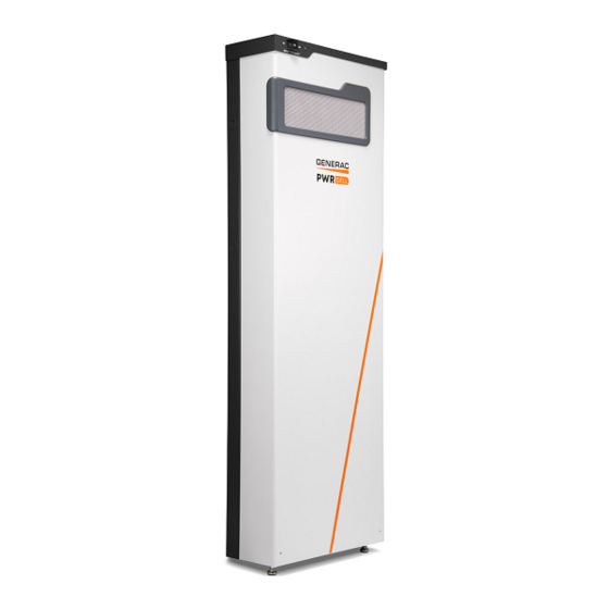
General Information About PWRcell Battery The PWRcell Battery is the storage component of the is directly connected to PV Links (B) and PWRcell PWRcell system. The battery can be used for grid- Battery (C) on the DC (REbus) lines (D). To the right of connected solar applications such as Self Supply, Rate the inverter are AC lines: 240VAC or 208VAC for grid and Arbitrage, and Clean Backup Power. -
Page 16: Component Locations
General Information Component Locations Battery Disconnect Switch DANGER Electrocution. Initiate a system-wide shutdown and turn the PWRcell DC Disconnect Switch OFF on all connected batteries before performing service. Failure to do so will result in death, serious injury, or equipment and property damage. -
Page 17: Section 3: Location And Compliance
Location and Compliance Section 3: Location and Compliance Location and Clearances • Do not expose the battery to extreme tempera- tures. See Specifications for recommended and PWRcell IR (Indoor Rated Model) acceptable operating temperatures. Operating the battery outside of the recommended range may Install the PWRcell Battery in dwelling units in the follow- degrade performance. -
Page 18: Compliance
Location and Compliance Compliance • Do not install where excessive amounts of water from roof runoff, landscape irrigation, water sprin- klers, or sump pump discharge could contact the DANGER enclosure. Loss of life. Property damage. Installation must • Do not install where water levels may rise and con- always comply with applicable codes, standards, laws tact the unit. -
Page 19: Section 4: Installing Pwrcell Battery
Installing PWRcell Battery Section 4: Installing PWRcell Battery Carton Contents Installing Battery Enclosure • Wall bracket WARNING • Lower wall mount and foot brackets (Outdoor Personal injury. Use caution when handling heavy parts and Rated model only). battery modules. Lift heavy parts in teams if necessary. Failure •... -
Page 20: Installing Foot Bracket (Or Model Only)
Installing PWRcell Battery Installing Foot Bracket (OR model only) Installing Wall Bracket • Mount foot bracket to wall with the following procedure: Figure 4-4. Bottom edge (A) is 29-5/8 in (752 mm) off the floor for IR installations. A template is included and will help locate the holes for both Wall and Foot Brackets. -
Page 21: Battery Knockout Locations (Ir And Or Models)
Installing PWRcell Battery Battery Knockout Locations (IR and OR models) 1-5/16 in (3.3 cm) 13-3/8 in (34 cm) 57-5/8 in 9-3/8 in (146.3 cm) (23.9 cm) 1-1/4 in (3.12 cm) 42-13/16 in 41-5/8 in (108.7 cm) (105.7 cm) 29-5/8 in (75.18 cm) 011210 Figure 4-6. -
Page 22: Placing Chassis Onto Bracket And Leveling Feet
Installing PWRcell Battery Placing Chassis onto Bracket and Leveling Feet 6. Verify there is minimum 1-3/4 in (4.45 cm) gap between the bottom of the body and the floor. 1. See Figure 4-7. Lift body (A) onto bracket (B). 7. Tighten machine screws to bracket and torque to Keep body tight to the wall while lowering body 13 in-lb (1.47 Nm). -
Page 23: Note On Dc Wiring And The Nec
Installing PWRcell Battery Remote Shutdown Switch Connec- To install REbus wiring: tions (If equipped) 1. See 4-9. Install REbus conductors to their Figure terminal blocks: RE+ to red (A), RE- to blue (B). NOTE: See Figure 4-10. The STOP terminals ship with 2. - Page 24 Installing PWRcell Battery NOTE: Select a code compliant switch rated for STOP 3. See Figure 4-13. The STOP terminals and circuit voltage of 12VDC minimum and current greater remote shutdown switch can be wired in par- than or equal to 1A. Switch must be listed and meet the allel.
-
Page 25: Connecting Blackstart Battery
Installing PWRcell Battery Connecting Blackstart Battery Figure 4-14. Connect blackstart battery lead to posi- tive battery terminal (E). NOTE: The negative lead is already connected to termi- nal (F). NOTE: Do not leave blackstart battery connected if PWRcell Battery is not connected to REbus. Blackstart battery will enter a sleep mode and discharge to support the unit. -
Page 26: Installing Battery Modules
• When installing battery modules, install top rear module first, regardless of configuration. • for the order of battery module and spacer installation for PWRcell M3 (B), PWRcell M4 (C), Figure 4-17 PWRcell M5 (D), and PWRcell M6 (E). NOTE: Module spacers (F) are required on PWRcell M3 (B) and M5 (D) configurations. -
Page 27: Installing Rear Modules
2. Fasten each grounding tab with a M4x8 mm SEMS Figure 4-21. Installing Front Battery Modules screw (M) torque to 13 in-lb (1.47 Nm). Installing Module Spacer (PWRcell M3 and PWRcell M5 only) Figure 4-22. Module spacers (O) must be installed on any single module shelf. -
Page 28: Installing Retention Clips
Installing PWRcell Battery 009935 Figure 4-24. Installing Module Spacer (2 of 3) 4. See Figure 4-25. Secure spacer with two M4X8 SEMS screws and torque to 13 in-lb (1.47 Nm). 009933 Figure 4-22. Module Spacer PWRcell Battery modules and upgrade kits can be obtained by contacting Generac Customer Service at 1- 888-436-3722 (1-888-GENERAC),... -
Page 29: Connecting Com Cables (Dcb And Ex Modules)
Installing PWRcell Battery 3. Secure retention clip to bracket with a M4X8 mm Figure 4-27. Note that there are three types of retainer clips: double retention clips (U), single retention screw and torque to 13 in-lb (1.47 Nm). clips marked O (T) and single retention clips marked X (S). -
Page 30: Connecting Battery Power Cables
Installing PWRcell Battery 4. Connect the other end of Black CAT5 jumper to COM IN port (D) on front battery module (C). 5. Connect Blue CAT5 cable to COM OUT port (E). 6. Connect the other end of Blue CAT5 cable to COM IN port (G) on lower, rear battery module (F). -
Page 31: Installing Cover
Installing PWRcell Battery Installing Cover 3. See Figure 4-33. Install loop jumper (C) on every unused power cord connector (D). 1. See Figure 4-35. Place cover (A) upright in front of unit. 2. Verify all cables are tucked in and clear of frame. 3. -
Page 32: Upgrading Pwrcell Battery
• A module spacer must be installed on any single module shelf. See Installing Module Spacer (PWRcell M3 and PWRcell M5 only). Using Vset Function NOTE: Perform Vset before installing new modules. NOTE: To perform Vset, the existing battery modules must be at higher voltages than the new modules. -
Page 33: Section 5: Commissioning
Commissioning Section 5: Commissioning General Information Configure Battery 1. Using the left or right arrow keys on the inverter NOTE: Register the PWRcell Inverter for commissioning control panel, navigate to the PWRcell Battery at https://pwrfleet.generac.com. device page and press the center button. Before commissioning PWRcell Battery verify all wiring is 2. -
Page 34: Battery Settings
Commissioning Battery Settings TABLE 1. Battery Settings Setpoint Range Default Description Channel for REbus communications. All devices in a PLM Channel 1 – 12 system must use the same channel (except REbus Beacon). Minimum state of charge (SOC) absolute- this is the MinSocAbsl 0 –... -
Page 35: Decommissioning
Commissioning Decommissioning Decommissioning Plan The owner of the PWRcell Battery and the qualified WARNING Generac Service Dealer shall prepare a written decommissioning plan that provides the overview of the Environmental Hazard. Always recycle batteries at an decommissioning process developed specifically for the official recycling center in accordance with all local battery that... - Page 36 Commissioning This page intentionally left blank. Installation Manual for Generac PWRcell Battery...
-
Page 37: Section 6: Wiring Diagrams
Wiring Diagrams Section 6: Wiring Diagrams PWRcell M3 BLACK Contactors Snubber Battery String I/O Switch Black-start battery G R B REbus 380v DC REbus cable entrance Module Cat 5 COMs Cable Front Module Spacer Module 2 Module 1 Module 3... -
Page 38: Pwrcell M4
Wiring Diagrams PWRcell M4 BLACK Contactors Snubber Battery String I/O Switch Black-start battery G R B REbus 380v DC REbus cable entrance Module CAT5 COMs Cable Front Module 1 Module 3 Module Jumpers Module 2 Module 4 Back 009946 Installation Manual for Generac PWRcell Battery... -
Page 39: Pwrcell M5
Wiring Diagrams PWRcell M5 BLACK Contactors Snubber Battery String I/O Switch Black-start battery G R B REbus 380v DC REbus cable entrance Module CAT5 COMs Cable Front Module Spacer Module 2 Module 4 Module Jumper Module 1 Module 5 Module 3 Back 009947 Installation Manual for Generac PWRcell Battery... -
Page 40: Pwrcell M6
Wiring Diagrams PWRcell M6 BLACK Contactors Snubber Battery String I/O Switch Black-start battery G R B REbus 380v DC REbus cable entrance Module Cat 5 COMs Cable Front Module 1 Module 3 Module 5 Module 2 Module 4 Module 6 Back 009948 Installation Manual for Generac PWRcell Battery... -
Page 41: Section 7: Troubleshooting
Troubleshooting Section 7: Troubleshooting General Troubleshooting Some of the more common problems are listed in the table below. This information is intended to be a check or verification that simple causes can be located and fixed. It does not cover all types of problems. Procedures requiring in-depth knowledge or skills should be referred to a Generac Authorized Service Dealer. - Page 42 Troubleshooting This page intentionally left blank. Installation Manual for Generac PWRcell Battery...
- Page 43 This page intentionally left blank.
- Page 44 ©2021 Generac Power Systems, Inc. S45 W29290 Hwy. 59 All rights reserved. Waukesha, WI 53189 Specifications are subject to change without notice. 1-888-GENERAC (1-888-436-3722) No reproduction allowed in any form without prior written www.generac.com consent from Generac Power Systems, Inc.
Need help?
Do you have a question about the PWRcell M3 and is the answer not in the manual?
Questions and answers