Table of Contents
Advertisement
User Manual CDN2000-06-25
Coupling Network for:
Supply input
Title:
Date:
Division Manager:
Quality Manager:
Revised
Three Phase Coupling Decoupling Network - Manually Operated
For EFT, SURGE, RING WAVE, OSCI Coupling
Surge: 1.2/50µs up to 6 kV and 8/20 current up to 3 kA
Ring Wave: up to 6 kV
EFT: up to 4.4 kV, common and differential mode
Damped Oscillatory Wave: up to 3kV
Filter and
Supply output
overcurrent trip
E-CDN2000-06-25-E-Manual
Switch field coupling
impedance and path
Ls ON/OFF
CDN2000-06-25 Coupling Network
16.07.99
M. Lutz
R. Henz
06. May 2011
1/54
Advertisement
Table of Contents

Related Manuals for EMC-PARTNER CDN2000-06-25


Summary of Contents for EMC-PARTNER CDN2000-06-25
- Page 1 User Manual CDN2000-06-25 Coupling Network for: Surge: 1.2/50µs up to 6 kV and 8/20 current up to 3 kA Ring Wave: up to 6 kV EFT: up to 4.4 kV, common and differential mode Damped Oscillatory Wave: up to 3kV...
-
Page 2: Table Of Contents
CDN2000-06-25 coupling decoupling network DESCRIPTION The different application of the CDN2000-06-25 1.1.1 "CWG Combination Wave Generator" 1.1.2 Ring wave test 0,5 µs / 100 kHz 1.1.3 Electric fast transient 5/50 ns 1.1.4 Damped Oscillatory Wave 100 kHz or 1 MHz Impulse testers useably with CDN2000-06-25 1.2.1... - Page 3 Ring Wave coupling set up 5.3.6 EFT coupling set up 5.3.7 Damped oscillatory coupling set up TESTING WITH THE CDN2000-06-25 Quickstart of TRA or MIG together with CDN2000-06-25 6.1.1 MIG0603Inx Operation with CDN2000-06-25 MAINTENANCE AND SERVICING Maintenance Verification of the CDN2000-06-25 by the user 7.2.1...
- Page 4 CDN2000-06-25 coupling decoupling network 10.2 Correction 10.2.1 TRA2000 with CDN2000 SURGE Synchronisation GLOSSARY INDEX ANNEX 13.1 Damped oscillatory on power supply 13.2 Damped oscillatory on I/O lines 13.3 Assembly Instruction to MC Connectors 13.4 Wire connection between MIG0603OMI and CDN2000-06-25 4/54...
-
Page 5: Description
Contact-protected construction. All plug connections to power supply and EUT are arranged on the front plate. 1.1 The different application of the CDN2000-06-25 1.1.1 "CWG Combination Wave Generator" The combination wave generator has been defined first for Electro Magnetic Compatibility EMC tests up to 4 kV in the document IEC 61000-4-5 or IEEE 587. - Page 6 CDN2000-06-25 coupling decoupling network Generators to carry out combination wave tests EUT, e.g. Motors Test generator CWG Figure: 1.0.3-1 Legend: Charging resistor Impulse capacitor High voltage switch Discharge resistor Inductance of the generator Serial resistor Shunt RE2 Discharge resistor Divider...
-
Page 7: Ring Wave Test 0,5 Μs / 100 Khz
CDN2000-06-25 coupling decoupling network Superimposing surge onto power supply To superimpose the surge pulses onto power line supply, coupling filters must be used. The aim of the coupling filter is to couple the generated surge waveform without deformation of rise time, half value time and amplitude onto the operated EUT and to protect the auxiliary equipment from surge pulses. - Page 8 CDN2000-06-25 coupling decoupling network ANSI / IEEE; IEC 61000-4-12 CWG versus Ring wave Lightning Household Equipment e.g. PC Secondary Protection Primary Protection Figure: 1.0.2-1 The ring wave appears at the terminals of equipment (equipment ports) as a consequence of switching in power and control lines, as well as a consequence of lightning.
- Page 9 CDN2000-06-25 coupling decoupling network A dc source charges the impulse capacitor Cs to a programmed voltage. The high voltage switch S links impulse capacitor to the impulse shaping network. Depending on energy and voltages it can be a mechanical or an electronic switch. The waveform is mainly influenced by the network of the generator.
-
Page 10: Electric Fast Transient 5/50 Ns
CDN2000-06-25 coupling decoupling network The same investigation put in evidence that reverse voltage applied during the conduction period of the power frequency produces lower breakdown voltage than the application of the transient with no load or during blocking. 1.1.3 Electric fast transient 5/50 ns Industrial measurement and control equipment practically always operates in conjunction with conventional control units (relays, contactors). - Page 11 CDN2000-06-25 coupling decoupling network respect, the resulting transient voltage and current in HV busbars are characterised by a fundamental oscillation frequency that depends on the length of the circuit and on the propagation time. The oscillation frequency ranges from about 100 kHz to a few megahertz, depending on the influence of the parameter mentioned above and the length of the busbars, which may vary from some tens of meters to hundreds of meters.
-
Page 12: Mig Testers With 6 Kv Output Voltage
The first two digit indicates the maximum output voltage of the tester and the next two digit the maximum output current. MIG0603IN Surge, Ring wave tester with single phase coupling decoupling network included. The CDN2000-06-25 can be used for three phase application with both waveforms up to 6 kV. MIG1203-CWG The MIG1203-CWG includes a a hybrid or combination circuit with a voltage wave shape 1,2/50 µs and a... -
Page 13: Technical Data
CDN2000-06-25 coupling decoupling network 1.3 Technical data 1.3.1 CDN2000-06-25 SURGE: Coupling: Connection between the impulse tester and the power supply line to the EUT. Coupling path Manual selection of the coupling path on the front panel, coupling impedance see tester manual 10 ... - Page 14 CDN2000-06-25 coupling decoupling network Ring Wave Coupling: Connection between the impulse tester and the power supply line to the EUT. Coupling path Manual selection of the coupling path on the front panel, coupling impedance see tester manual IEC 61000-4-12 L1-PE, L2-PE, L3-PE, N-PE...
-
Page 15: Block Diagram Cdn2000
CDN2000-06-25 coupling decoupling network 1.3.2 Block diagram CDN2000 Original drawings see appendix of the manual Output EUT Coupling path switching Power input Filter Output I/O lines 1Mhz 100 kHz tests 15/54... -
Page 16: Mechanical Dimensions
CDN2000-06-25 coupling decoupling network 1.4 Mechanical dimensions 1.4.1 CDN2000-06-25 Tester Type Dimensions [mm] Weight [kg] Versions l x w x h width x depth x height CDN2000-06-25 450 x 500 x 190 19" Rack 4 UH 1.5 Power supply No power supply is necessary. - Page 17 CDN2000-06-25 coupling decoupling network 1.6 Accessories delivered with the CDN2000-06-25 1.6.1 Included articles 1.6.2 Standard accessories 17/54...
- Page 18 CDN2000-06-25 coupling decoupling network 18/54...
-
Page 19: Safety
EMC compatibility chapter. Tab. 2.2 The CDN2000-06-25 should be operated in a dry, clean room. If for any reason water condenses in the CDN2000-06-25, then no CDN2000-06-25 operation should be started before the unit is dry. It is strictly forbidden to operate the CDN2000-06-25 generators in rooms with of gas explosion risk. -
Page 20: Precautionary Measure During Use
Never touch the EUT when a test is in operation. Touch no connectors of connection cable when a EMC test is in operation. The high voltage of the CDN2000-06-25 and the power on the EUT must turned off before a manipulation on the EUT is carried out. -
Page 21: Mechanical Structure
The other half is to be connected to the test object. Caution! Only the delivered cable and accessories are allowed to use with the CDN-2000! The weight of the filter is 28 kg. E-CDN2000-06-25-E-Manual 21/54... - Page 22 CDN2000-06-25 coupling decoupling network 22/54...
-
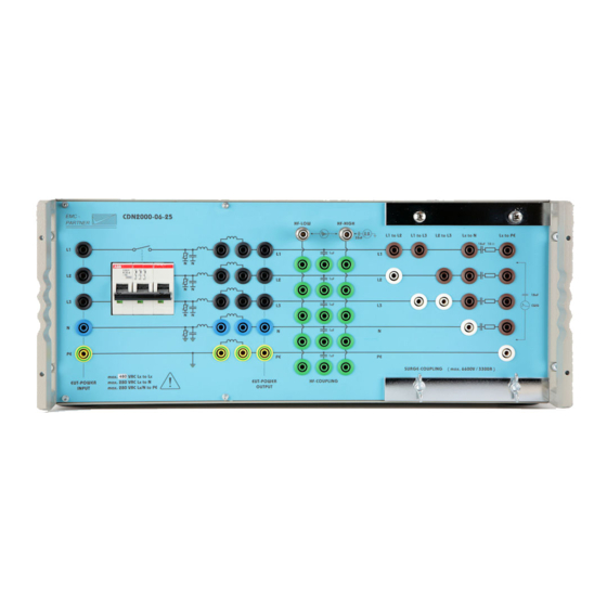
Page 23: Panels Of The Cdn2000-06-25
4 Panels of the CDN2000-06-25 4.1 Front panel of the CDN2000-06-25 Filter and Supply input Switch field coupling Supply output overcurrent trip impedance and path Ls ON/OFF For fusing, a combined circuit breaker is built in. The trip point lies slightly above the nominal current level and therefore only causes a separation by a moderate continuous overload. - Page 24 CDN2000-06-25 coupling decoupling network 24/54...
-
Page 25: Preparation For Operation
Before you unpack the CDN2000-06-25, please check whether the packing is deformed or damaged. When the CDN2000-06-25 is unpacked, also check whether the tester is damaged. If you detect a damage, please inform EMC PARTNER and the shipping organisation immediately. -
Page 26: Eut Power, Power Source For The Eut
To connect the EUT Power Input with the public power supply please cut the three black, blue and green/yellow cables supplied into two halves of the same length. One half used for the EUT Power connection to the CDN2000-06-25, and the other half for supplying the EUT. 5.3.3 I/O lines coupling... -
Page 27: Surge Coupling Set Up
CDN2000-06-25 coupling decoupling network 5.3.4 SURGE coupling set up Surge coupling L to PE The CWG part of MIG or TRA are equipped with 18 µF Surge coupling network The SURGE coupling is clearly organised as shown in the above photograph For couplings between the phases or phase and neutral, 18 µF is switched in as a coupling element. -
Page 28: Eft Coupling Set Up
CDN2000-06-25 coupling decoupling network The Ring Wave coupling is clearly organised as shown in the above photograph. All coupling path are equal as for the SURGe coupling except the coupling to protective earth. The coupling L to PE must be made as showed in the figure above (no additional resistor or capacitor in circuit). -
Page 29: Damped Oscillatory Coupling Set Up
To synchronise the EFT onto one of the phase L1 to L3 the surged phase must be connected to the TRA2000 rear side EUT-power . Use the black banana cable length 1 m. The neutral and the protective earth must be connected on the rear side of the testers and the CDN2000-06-25 (colour blue and yellow green). - Page 30 CDN2000-06-25 coupling decoupling network 30/54...
- Page 31 6 Testing with the CDN2000-06-25 6.1 Quickstart of TRA or MIG together with CDN2000-06-25 For MIG operation refer to the MIG manual and for TRA operation refer to TRA manual section "Quickstart". All connection must made as described in chapter 5 at the rear and the front panel of the CDN.
- Page 32 CDN2000-06-25 coupling decoupling network The supply power of the EUT should be switched on with the magnetic over current switch as shown above. 32/54...
-
Page 33: Maintenance And Servicing
SURGE U-CRO for the voltage measurement at no load SURGE I-CRO for current measurement at short circuit (make a short circuit on the EUT power output phase to neutral on the front panel of the CDN2000-06-25 generator) 3. Settings at the oscilloscope Time base 5 µs,... -
Page 34: Ring Wave Tester
7.3 Verification of the CDN2000-06-25 at EMC PARTNER EMC PARTNER verify the CDN2000-06-25 in accordance with IEC 61000-4-5 standard. Before a CDN2000-06-25 is delivered, all verifications are carried out in accordance with the basic documents. See separate test report of CDN2000-06-25 attached to this manual, or delivered with the CDN. -
Page 35: What Must Be Done Following Failed Operation
8 What must be done following failed operation 8.1 Service; Repairs The CDN2000-06-25 is a compact equipment and servicing or repairing the tester can only be carried out by EMC PARTNER authorised service companies. 8.2 Spare parts list No spare parts are necessary for the MIG. - Page 36 CDN2000-06-25 coupling decoupling network 36/54...
-
Page 37: Service Department Of Emc Partner Ag
There is no danger involved in dismantling the CDN2000-06-25. 8.6 Parts which can be recycled The CDN2000-06-25 contains parts made from steel, aluminium, PVC, two-component sealing compound. The impulse capacitors are filled with non-poisonous mineral oil. The various parts can be separated and recycled. - Page 38 CDN2000-06-25 coupling decoupling network 38/54...
-
Page 39: Recycling / Disposal
9.2 WEEE directive 2002/96/EG The EMC Partner CDN2000-06-25, is exempted from the directive 2002/96/EG (WEEE) under category 9. The product should be recycled through a professional organisation with appropriate experience for the disposal and recycling of electronic products. EMC Partner are also available to help with questions relating to the recycling of this product. - Page 40 CDN2000-06-25 coupling decoupling network 40/54...
-
Page 41: Appendix And Correction
Surge current front time T1= 8 µs ±20% 6.4 - 9.6 µs Time to half value T2=20 µs ±20% 16 - 22 µs measure Imax Check the source impedance: Umax / Imax = 2 Ohm ±10% E-CDN2000-06-25-E-Manual 41/54... - Page 42 CDN2000-06-25 coupling decoupling network 10.2 Correction 10.2.1 TRA2000 with CDN2000 SURGE Synchronisation Different possibilities exist to Synchronize the TRA-generator with a three phase coupling filter. Example: SURGE impulse must synchronized with the phase L1 to PE. Set the black banana plugged cable for...
- Page 43 Short-term mains failure or loss of voltage International Standardisation for Electro-technology VARIAC Adjustable auto-transformer SPIKE A pulse during an EFT or Burst package Cathode-Ray Oscilloscope High voltage Root-mean square (effective) value E-CDN2000-06-25-E-Manual 43/54...
- Page 44 CDN2000-06-25 coupling decoupling network Used symbols: Direct current Alternating current Three phase alternating current Earth (ground) terminal Protective conductor terminal IEC 417, No. 5019 Caution, risk of electric shock ISO 3864, No. B.3.6 Caution (refer to accompanying documents) ISO 3864, No. B.3.1...
- Page 45 12 Index 10/700 µs Tester Maintenance Verification by the customer Mechanical dimensions CDN2000-06-25 Tester MIG tester 6 kV General Attention refer to manual 22; 27 Operational Conditions CDN2000 Block diagram Technical Data Check before operation Packaging and shipment Climatic Condition...
- Page 46 CDN2000-06-25 coupling decoupling network Verification by EMC PARTNER 46/54...
- Page 47 CDN2000-06-25 coupling decoupling network 47/54...
- Page 48 CDN2000-06-25 coupling decoupling network 13 Annex 13.1 Damped oscillatory on power supply Power output Power input Remove all 5 L1, L2, L3, N, L1, L2, L3, N, bridges 13.2 Damped oscillatory on I/O lines I/O lines Remove power I/O lines...
- Page 49 CDN2000-06-25 coupling decoupling network 13.3 Assembly Instruction to MC Connectors 49/54...
- Page 50 CDN2000-06-25 coupling decoupling network 50/54...
- Page 51 CDN2000-06-25 coupling decoupling network 13.4 Wire connection between MIG0603OMI and CDN2000-06-25 51/54...
- Page 52 CDN2000-06-25 coupling decoupling network 52/54...
- Page 53 CDN2000-06-25 coupling decoupling network 53/54...
- Page 54 CDN2000-06-25 coupling decoupling network 54/54...
Need help?
Do you have a question about the CDN2000-06-25 and is the answer not in the manual?
Questions and answers