
Related Manuals for Ricoh 1 Bin Tray BN1030


Summary of Contents for Ricoh 1 Bin Tray BN1030
- Page 1 1 Bin Tray BN1030 Machine Code: D574 Field Service Manual Ver 1.0 Latest Release: Nov, 2016 Initial Release: Nov, 2016 Copyright (c) 2016 Ricoh Co.,Ltd.
- Page 3 Symbols and Abbreviations This manual uses several symbols and abbreviations. The meaning of those symbols and abbreviations are as follows: Symbol What it means Screw Connector Clamp Short Edge Feed Long Edge Feed Black Cyan Magenta Yellow B/W, BW Black and White Full color [A] Short Edge Feed (SEF) [B] Long Edge Feed (LEF)
-
Page 5: Table Of Contents
Table of Contents Replacement and Adjustment ..........................2 Beforehand ................................2 1-Bin Tray Paper Remaining Sensor ........................3 1-Bin Tray Exit Sensor ............................4 1-Bin LED Board ..............................5... -
Page 6: Replacement And Adjustment
1.Replacement and Adjustment 1. Replacement and Adjustment Beforehand • Before installing options, please do the following: If there is a fax unit in the machine, print out all messages stored in the memory, the lists of user- programmed items, and the system parameter list. If there are printer jobs in the machine, print out all jobs in the printer buffer. -
Page 7: 1-Bin Tray Paper Remaining Sensor
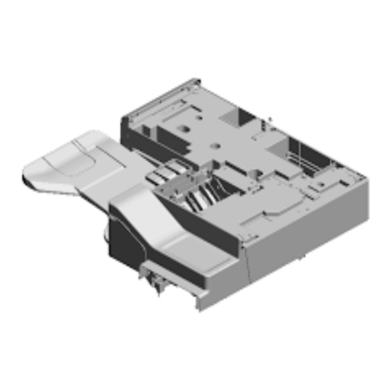
1.Replacement and Adjustment 1-Bin Tray Paper Remaining Sensor Remove the 1-bin tray unit. (See “1 Bin Tray BN1030” in the mainframe service manual) Remove the 1-bin tray upper cover [A]. ( × 3) Remove the 1-bin tray paper remaining sensor bracket [A]. ( ×... -
Page 8: 1-Bin Tray Exit Sensor
1.Replacement and Adjustment 1-Bin Tray Exit Sensor Remove the 1-bin tray unit. (See “1 Bin Tray BN1030” in the mainframe service manual) Remove the 1-bin tray upper cover. (1-Bin Tray Paper Remaining Sensor) Remove the 1-bin tray exit sensor bracket [A]. ( ×... -
Page 9: 1-Bin Led Board
1.Replacement and Adjustment 1-Bin LED Board Remove the 1-Bin tray unit. (See “1-Bin Tray BN1030” in the mainframe service manual) Remove the 1-bin LED board cover [A]. ( × 1) Remove the 1-bin LED board [A]. ( × 1)
Need help?
Do you have a question about the 1 Bin Tray BN1030 and is the answer not in the manual?
Questions and answers