Danfoss Optyma Plus Application Manuallines
Hide thumbs
Also See for Optyma Plus:
- User manual (19 pages) ,
- Instructions manual (36 pages) ,
- Manual (48 pages)

Related Manuals for Danfoss Optyma Plus


Summary of Contents for Danfoss Optyma Plus
- Page 1 Application guidelines Optyma Plus INVERTER ™ Stepless capacity modulation from 30 to 100 rps in a simple plug and play package Optyma EcoDesign by Danfoss 2018 cc.danfoss.com...
-
Page 3: Table Of Contents
Application Guidelines Content Important information/Safety ....4 System design recommendations ..26 1.1 Symbols are shown left of the text ..... 4 5.1 Piping design ..........26 5.2 Evacuation ............27 Product description .........5 5.3 Refrigerant charge ..........28 2.1 Optyma Plus INVERTER condensing unit ... 5 ™... -
Page 4: Important Information/Safety
Application Guidelines Important information/Safety 1.1 Symbols are shown There are 3 symbols, used for different degrees of This guideline is intended to enable users to left of the text danger: ensure the safe installation, starting, operation and maintenance of Optyma ™... -
Page 5: Optyma ™ Plus Inverter Condensing Unit
Application Guidelines Product description 2.1 Optyma Plus INVERTER ™ Optyma ™ Plus INVERTER combines our market • Oil separator with oil heater condensing unit leading expertise in condensing unit design with the unique benefits of stepless inverter scroll • Receiver with stop valve technology. -
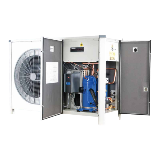
Page 6: Product Description
21-12-20 DATE APPD connection 16: Low pressure switch 28: Discharge pipe Confidential: Property of Danfoss Com by third party. Two or three dimensio 4: EMI filter (drive) 17: Microchannel heat exchanger 29: Condenser outlet pipe 5: Oil return pipe 18: Right side door... -
Page 7: Condensing Unit Nomenclature System
E: Housing Service Pressure YY = year of production F: Supply voltage, M§aximum Current Consumption G: Serial Number and bar code H: Protection For more information related to EcoDesign compliance, please refer to Coolselector® EcoDesign coolselector.danfoss.com or contact Danfoss 2018 FRCC.PC.044.A6.02... -
Page 8: Approvals And Certificates
* For service replacement of controller in Optyma ™ Plus INVERTER only new version of controller can be used: code number on the controller is 084B8080. NOTICE For service purpose original components (spare parts) recommended by Danfoss should be used. FRCC.PC.044.A6.02... -
Page 9: Cooling Capacities, Sound Data, Power Consumption
[2] Rated conditions, Evaporating temperature -10°C. Ambient air temperature +32°C. Return Gas Temperature 20°C Q [W], Cooling Capacity P [W], Power Input For more information related to EcoDesign compliance, please refer to Coolselector® EcoDesign coolselector.danfoss.com or contact Danfoss 2018 FRCC.PC.044.A6.02... - Page 10 [2] Rated conditions, Evaporating temperature -10°C. Ambient air temperature +32°C. Return Gas Temperature 20°C Q [W], Cooling Capacity P [W], Power Input For more information related to EcoDesign compliance, please refer to Coolselector® EcoDesign coolselector.danfoss.com or contact Danfoss 2018 FRCC.PC.044.A6.02...
- Page 11 [2] Rated conditions, Evaporating temperature -10°C. Ambient air temperature +32°C. Return Gas Temperature 20°C Q [W], Cooling Capacity P [W], Power Input For more information related to EcoDesign compliance, please refer to Coolselector® EcoDesign coolselector.danfoss.com or contact Danfoss 2018 FRCC.PC.044.A6.02...
- Page 12 [2] Rated conditions, Evaporating temperature -10°C. Ambient air temperature +32°C. Return Gas Temperature 20°C Q [W], Cooling Capacity P [W], Power Input For more information related to EcoDesign compliance, please refer to Coolselector® EcoDesign coolselector.danfoss.com or contact Danfoss 2018 FRCC.PC.044.A6.02...
-
Page 13: Layout
Application Guidelines Product description 2.9 Layout OP-MPLM028-035-044, OP-MPPM028-035-044 FRCC.PC.044.A6.02... -
Page 14: Application Range
Application Guidelines Application range 3.1 Main applications Optyma ™ Plus INVERTER is a perfect cooling Optyma ™ Plus INVERTER outdoor condensing solution for typical MBP applications like food units are released for R448A/R449A, R407A/F and retail, petrol forecourt sites, cold rooms ,and R404A. -
Page 15: Application Envelopes
Application Guidelines Application range 3.3 Application envelopes The operating envelopes of Optyma ™ Plus for condensing units with refrigerants R448A/ INVERTER are given in the figures below, where R449A, R407A/F and R404A. The operating limits the ambient and evaporating temperatures serve to define the envelopes within which represent the range for steady state operation. -
Page 16: Ambient Conditions
The CDS803 drive forces the compressor to 50rps (see Optyma Controller parameter c47) for 30s ambient temperature from -15°C to 43°C. For altitudes above 2000 m, contact Danfoss. The always at compressor start, to ensure proper oil other working conditions should be within the return at low load and short runtimes. -
Page 17: Installation
(not part of the Danfoss supply). wind. For example if the air leaving the condenser Installation of unit shall not be done in aggressive faces the prevailing wind, the air flow through and dusty environments. -
Page 18: Electrical Connection
Application Guidelines Installation WARNING 4.2 Electrical connection Ensure that power supply Below table lists recommended wiring sizes for cannot be switched on during installation. the condensing unit power supply cables. These wiring sizes are valid for a cable length up to 30 m. Model Cable size, mm (from network to unit main switch) -
Page 19: Wiring Diagrams
Application Guidelines Installation 4.3 Wiring diagrams OP-MPLM028-035-044, OP-MPPM028-035-044 A1 : EMC/RFI Filter (Compressor) A2 : Frequency Converter A3 : EMI Filter (Controls) A4 : Optyma ™ Plus Controller B1 : Condensing Pressure Transducer B2 : Suction Pressure Transducer B3 : High Pressure Switch B4 : Low Pressure Switch C1 : Run Capacitor (Fan) F1 : Fuse (Control Circuit) -
Page 20: Emergency Running Without Controller
Application Guidelines Installation 4.3.1 Emergency running In case of controller failure, the condensing unit wire 1 to drive terminal 55 without controller can still be operated when the controller standard wire 2 to drive terminal 53 wiring (WD1) is modified into a temporary wiring wire 3 to drive terminal 50 (WD2) as described below. - Page 21 Application Guidelines Installation OP-MPLM028-035-044, OP-MPPM028-035-044- Emergency Wiring A1 : EMC/RFI Filter (Compressor) A2 : Frequency Converter A3 : EMI Filter (Controls) A4 : Optyma ™ Plus Controller B1 : Condensing Pressure Transducer B2 : Suction Pressure Transducer B3 : High Pressure Switch B4 : Low Pressure Switch B5* : Fan Speed Controller / Pressure Switch C1 : Run Capacitor (Fan)
- Page 22 Application Guidelines Installation Picture1. Normal wiring Picture2. Emergency wiring FRCC.PC.044.A6.02...
-
Page 23: Electrical Protection Standard (Protection Class)
Application Guidelines Installation 4.4 Electrical protection - Scroll compressors: IP22 WARNING standard (protection - Fan: IP54 Power connections under class) - Controller: IP20 voltage and can cause danger by electrical shock. - Drive: IP20 - Complete unit: IP54 Optyma ™ Plus INVERTER units are fully wired and factory tested. -
Page 24: Phase Sequence
For specific applications not covered herein, please contact Danfoss for further information. It is compulsory to braze with a protective atmosphere of nitrogen inside the piping. Nitrogen displaces the air and prevents the formation of copper oxides in the system. -
Page 25: High Pressure Transmitter Connection
(Copper oxide could block capillary tubes, thermal (Insulation should be at least 19 mm thick and is expansion valves and generate damage of not a part of Danfoss supply). Use only dry pipes compressor). and components in order to avoid moisture in the system. -
Page 26: System Design Recommendations
Application Guidelines System design recommendations 5.1 Piping design Connection sizes! Unsuitable refrigerant flow Pipe runs should be kept as short as possible, rate! using the minimum number of directional changes. Use large radius bends and avoid NOTICE Do not assume that the liquid/ trapping of oil and refrigerant. -
Page 27: Evacuation
Application Guidelines System design recommendations NOTICE Diameter of separate suction lines from The installer is responsible for the evaporators to condensing unit manifold should installation of the unit and complete refrigeration be with appropriate size according evaporator system design according particular conditions capacity (securing recommended speed for proper of each application as this is not scope of current oil return). -
Page 28: Refrigerant Charge
Application Guidelines System design recommendations 5.3 Refrigerant charge For the initial charge condensing must not run charging operation must be done in liquid phase and eventual service valves must be closed. as far away as possible from the compressor. Charge refrigerant as close as possible to the nominal system charge before starting the Never start the compressor under vacuum, ensure compressor. -
Page 29: Oil Level
0,3l oil. In case of adding oils always installation lines exceed 20 m, additional oil may use original Danfoss POE oil from new cans. be needed. Oil charge has to be adjusted based on the oil level in the compressor sight glass. -
Page 30: Startup Of The Unit
Application Guidelines System design recommendations 5.6 Startup of the unit After below steps are completed: for Min Condensing Pressure. Scroll fast through 1) System is completely installed. the Parameters with a long press on these buttons. 2) All electrical connections are done. •... -
Page 31: Condensing Unit Controller
Application Guidelines Condensing unit controller In order to provide the highest level of compressor variable conditions condensing unit is equipped protection, energy efficiency and adaptation to with specific controller. 6.1 Advantages • Condensing pressure control in relation to • Built-in clock function with power reserve . outside temperature. -
Page 32: Maximum Discharge Gas Temperature
Application Guidelines Condensing unit controller 6.7 Maximum discharge The temperature is recorded by sensor Td. set delay time, the compressor will be stopped. gas temperature If variable speed control is chosen for the The compressor will only be re-started once the compressor, this control will initially reduce the temperature is 10 K lower than the set value. -
Page 33: Controller Settings
Application Guidelines Condensing unit controller 6.12 Controller settings NOTE! In case of controller replacement beware that unit controller settings are different from default controller factory settings! Default Unit controller Function Code Min.value Max.value controller settings settings Normal operation Set point Tc (regulation reference follows the number of degrees 2.0 K 20.0 K 8.0 K... - Page 34 Application Guidelines Condensing unit controller Default Unit controller Function Code Min.value Max.value controller settings settings Readout of fan speed in % Permitted change in fan speed (to a lower value) % per second 1,0% 5,0% 1,0% Jog speed (speed as a % when the fan is started) 100% Jog speed at low temperature Definition of fan control: 0=Off;...
- Page 35 Application Guidelines Condensing unit controller Default Unit controller Function Code Min.value Max.value controller settings settings Read-out of operating time of heating element in crankcase. (Value must be multiplied by 1,000). The value can be adjusted Read-out of number of HP alarms. The value can be adjusted Read-out of number of LP alarms.
-
Page 36: Service And Maintenance
Application Guidelines Service and maintenance 7.1 General Furthermore following should be checked: WARNING recommendations Even if main switch of 1. Electrical and refrigerant connections for condensing unit is in position OFF power still damages, corrosion etc. available at income terminals of main switch. 2. -
Page 37: Access Ports
Application Guidelines Service and maintenance 7.4 Access ports Charging port (suction line) - adjustment of refrigerant charge Charging port (liquid line) - initial charge (=4kg) FRCC.PC.044.A6.02... -
Page 38: Transportation, Handling And Storage
In the event you detect a copy of which should be sent responsible any damage, please contact your forwarder contact in Danfoss. 8.2 Transportation and Move the condensing unit only with appropriate jack. Use appropriate and safe lifting equipment. -
Page 39: Warranty
Danfoss). Annulment of warranty • Use of a refrigerant or lubricant not approved by from Danfoss side will also take place if the unit is Danfoss. altered without written approval from Danfoss. • Any deviation from recommended instructions... -
Page 40: Data Collected During Start Up
Application Guidelines Data collected during start up Identification Country Installation reference (shop name) City of installation Installer Company Unit Code/Type Serial N° of unit Installation Date Commission Date Installation Refrigerant Number of evaporators connected to the variable speed condensing unit Expected maximum Ambient temperature °C Expected minimum Ambient temperature °C Evaporators... - Page 42 Our products can be found in a variety of applications such as rooftops, chillers, residential air conditioners, heatpumps, coldrooms, supermarkets, milk tank cooling and industrial cooling processes. cc.danfoss.com Danfoss Commercial Compressors, BP 331, 01603 Trévoux Cedex, France | +334 74 00 28 29 © Danfoss | DCS (CC) | 2018.06 FRCC.PC.044.A6.02...
Need help?
Do you have a question about the Optyma Plus and is the answer not in the manual?
Questions and answers