Eaton NRX Series User Manual
Low voltage power (air) circuit breakers
Hide thumbs
Also See for NRX Series:
- Installation instructions manual (68 pages) ,
- Instruction leaflet (29 pages) ,
- Installation and removal instructions (25 pages)
Table of Contents
Advertisement
Advertisement
Table of Contents

Related Manuals for Eaton NRX Series


Summary of Contents for Eaton NRX Series
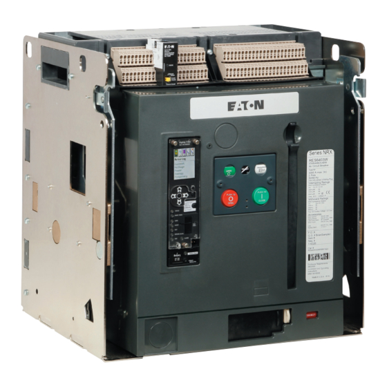
- Page 1 Instructional Book MN01301003E effective July 2011 Series NRX Series NRX Low Voltage Power (Air) Circuit Breakers User Manual Instructions apply to: Series NRX, Type RF Frame IEC, IZMX40 4000 NRX RF DRAWOUT SUBTITLE IMAGE (12/15/2010) Typical Drawout Circuit Breaker and Cassette...
-
Page 2: Table Of Contents
Figure 17 . CONNECT Position Figure 18. Step 2 Figure 18a. Step 2 Figure 19. Step 3 Figure 20. Step 4 Figure 21. Step 1 Figure 22. Step 2 Figure 23. Step 3 Figure 24. Step 3 EATON CORPORATION www.eaton.com... -
Page 3: List Of Tables
Table 1. Transport Indicator Table 2. Suggested Lifting Procedures and Precautions Table 3. Approximate Weights Table 4. Series NRX Digitrip Trip Units Table 5. Customer Wiring Details Table 6. Inspection Frequency Table 7 . Circuit Breaker Troubleshooting Guide EATON CORPORATION www.eaton.com... -
Page 4: Section 1: Introduction
Eaton accordance with IEC 60947-2 requirements. The Series NRX range is representative. -
Page 5: Figure 1. Series Nrx Nameplate Location
Rated short time withstand Third party certification markings Factory installed ,V ,V accessories Order information Mnf. date code 20-digit catalog string (YYMMDD) Mnf. barcode Additional third party markings Breaker manual (EN) Mnf. location Figure 1. Series NRX Nameplate Location EATON CORPORATION www.eaton.com... -
Page 6: Figure 2. Series Nrx Catalog Numbering System
LSIGA ARMS 18 LSIGA ARMS 19 Position 8 Mounting Config. Drawout Position 11 Rating Plug (Amperes) Fixed Non-Auto Switch 1000 1250 1600 2000 2500 3200 4000 Figure 2. Series NRX Catalog Numbering System (continued on next page) EATON CORPORATION www.eaton.com... - Page 7 8 Form C (8a/8b) Future 10 Form C (10a/10b) 12 Form C (12a/12b) Terminals ship as kit with breaker and cassette (option not available with 4000A Frame Rating) Figure 2. Series NRX Catalog Numbering System (continued from previous page) EATON CORPORATION www.eaton.com...
-
Page 8: Figure2A. Series Nrx Type Rf-Frame Cassette Catalog Numbering System
Refer to Section 5 for mounting and installation dimensional NRX breaker. information. Electronic files of dimensional drawings for customer use are available for download at www.eaton.com/seriesnrx. Drawout breaker and cassette Fixed circuit breaker A drawout circuit breaker is used in combination with a drawout cassette (Figures 3 and 4). -
Page 9: Figure 3. Typical Nrx Drawout Circuit Breaker
5. Plug Connector for Secondary Contacts 6. Primary Finger Cluster 7 . Phase Barriers (optional) 8. Levering Mechanism 9. On Board Lev-in Tool Figure 3. Typical NRX Drawout Circuit Breaker Refer to Figure 6 for more visual details of front cover. otee: EATON CORPORATION www.eaton.com... -
Page 10: Figure 4. Typical Nrx Drawout Cassette
4. Interlock Plate/Pins 5. Grounding (earthing) Bar 6. Gas Ventilation Opening 7 . Stationary Primary Contacts 8. Safety Shutters (optional) 9. Primary Terminal Pad 10. Barrier (optional) 11. Secondary Wiring Point Identification Figure 4. Typical NRX Drawout Cassette EATON CORPORATION www.eaton.com... -
Page 11: Figure 5. Typical Nrx Fixed Circuit Breaker
3. Arc Chute Cover 4. Lifting Handle 5. Primary Terminal Pad 6. Secondary Point Identification 7 . Installation Mounting Feet Figure 5. Typical NRX Fixed Circuit Breaker Refer to Figure 6 for more visual details of front cover. otee: EATON CORPORATION www.eaton.com... -
Page 12: Figure 6. Typical Nrx Drawout Circuit Breaker Front Cover
13. Breaker Key Lock (Optional) 14. Contact Status 15. Ready-to-close Status Flag 16. Mechanism Spring Status 17 . Manual OFF 18. Manual ON 19. Padlock Pushbutton Cover Mounting Holes Figure 6. Typical NRX Drawout Circuit Breaker Front Cover EATON CORPORATION www.eaton.com... -
Page 13: Section 2: Receiving, Unpacking, And Inspection
Inspect shipping containers for obvious signs of external damage. Record any observed damage for reporting to the transportation carrier and Eaton. All reports and claims should be as specific as possible and include the order number and other applicable nameplate information. -
Page 14: Table 2. Suggested Lifting Procedures And Precautions
Table 2. Suggested Lifting Procedures and Precautions When using an appropriate overhead lifting device, attach the lifting harness in the locations as shown below that best fits the circumstance (Upright Cassette) (Breaker in Cassette) (Cassette Front Up) (Breaker Only) EATON CORPORATION www.eaton.com... -
Page 15: Figure 7 . Step
Check to make sure that the installed trip unit and nameplate information match the equipment as ordered. All circuit breakers should be operated as described in Section 3 prior to being put into service. (Breaker in Drawout Cassette) EATON CORPORATION www.eaton.com... -
Page 16: Section 3: Breaker General Operation
Step 2e: Lower both rails down into their extended and locked position. Step 4e: To remove the breaker from the cassette lower both rails down into their extended and locked position. Using the charging handle pull the breaker out onto the extension rail. EATON CORPORATION www.eaton.com... -
Page 17: Figure 13. Step 4
• CONNECT (Figure 17) The WITHDRAWN position is outside the compartment on the cassette’s drawout rails. The DISCONNECT, TEST, and CONNECT positions are reached by means of the levering mechanism and can be achieved with the assembly door closed. EATON CORPORATION www.eaton.com... -
Page 18: Figure 16. Test Position
The Detent will engage at each discrete position (Disconnect, Test, Connect) and requires the user to manually reset the system before proceeding to the next position. EATON CORPORATION www.eaton.com... -
Page 19: Figure 19. Step 3
It is possible to manually recharge the Figure 20. Step 4 spring immediately after closing the breaker, before it has been tripped open. The status of the spring (charged or discharged) is indicated in the mechanism spring status window just above the pushbuttons. EATON CORPORATION www.eaton.com... -
Page 20: Figure 22. Step 2
For electrical closing, a Latch Check Switch (LCS) option is available Figure 23. Step 3 that will block the application of the electrical close command until the breaker is ready. EATON CORPORATION www.eaton.com... -
Page 21: Section 4: Circuit Breaker Features And Accessories
IL01301051E (Digitrip 520) or IL01301064E (Digitrip 1150), which Table 4. Series NRX Digitrip Trip Units are dedicated to the trip units and are available on Eaton’s web site. Functions Digitrip 520... -
Page 22: Figure 26. Secondary Point Identifications
PT Module) of mounting most accessory items are maintained. Non-automatic breakers are tested in keeping with IEC 60947-2 requirements. Master Connection NF Master Connection RF 30 32 76 78 (Left Side) (Right Side) Figure 26. Secondary Point Identifications EATON CORPORATION www.eaton.com... -
Page 23: Figure 27. Secondary Terminal Blocks
AWG and are UL/CSA rated for 600V, 10A. 8. The recommended wire strip length is 10mm (.394”). 9. The tension clamp terminals also support finely stranded con- ductors with wire-end ferrules and plastic collars DIN 46228/4, rated connection. EATON CORPORATION www.eaton.com... -
Page 24: Figure 28. Weidmuller Plug And Crimp Contact
Available accessories are discussed in general terms. For more detailed information and/or installation instructions, refer to individual instruction leaflets dedicated to individual items. Figure 31. Right Accessory Tray EATON CORPORATION www.eaton.com... - Page 25 Other internal electrical devices • Cassette safety shutters There are three types of internally mounted electrical devices: • Door escutcheon • Spring release • IP55 waterproof cover • Latch check switch • Mechanical interlock • Motor operator EATON CORPORATION www.eaton.com...
- Page 26 (prevents closure) when others are The indicator is reset manually by pushing it back in. If the interlocked closed. Consult Eaton for details. indicator is not reset, the circuit breaker will not close until the indicator is pushed back in.
- Page 27 IL for Handheld Test Kit IL5721B13 NF and RF IL for Draw out Cassette IP20 Safety Shutters IL01301044E IL for Time Delay Undervoltage Module IL5721B33 NF and RF IL for Neutral Current Sensor IL01301046E IL for Cassette Extension Rails IL01301047E EATON CORPORATION www.eaton.com...
-
Page 28: Section 5: Dimensional Drawings For Installation Of Drawout Circuit Breaker And Cassette
Must Use Reduced Head Height .43 (11) Hardware at These Locations 4X Ø.35 (9) 5.13 3.85 (103,2) .35 (9) (97 ,8) .43 (11) 5.25 (133,4) 3X 15.14 (384,6) 16.77 (425,8) Figure 32. Three-Pole Drawout Cassette—Rear/Bottom Views in Inches (mm) EATON CORPORATION www.eaton.com... - Page 29 (30˚ Free Travel) 14.25 (361,8) 5.84 (4,1) (148,4) .16 (4) .86 (21,9) 1.00 (25,4) .36 (9,1) 14.48 (367,8) Connected Position 2.17 (55,1) .58 (14,8) Test Position Figure 33. Three-Pole Drawout Cassette—Side Views CONNECTED and TEST Positions in Inches (mm) EATON CORPORATION www.eaton.com...
- Page 30 Series NRX Low Voltage Power (Air) MN01301003E Circuit Breakers User Manual Effective July 2011 1.28 2.87 (32,6) (72,9) Disconnected Position 12.55 (318,7) 14.06 (357) Withdrawn Position Figure 34. Three-Pole Drawout Cassette—Side Views DISCONNECTED and WITHDRAWN Positions in Inches (mm) EATON CORPORATION www.eaton.com...
- Page 31 .98 (25) 4.53 (115) Optional Barrier 4.53 (115) 4.53 (115) 6.06 (154) 3x 2.99 3.85 (76) (97,9) 5.65 (143,5) 5.20 (132,1) 4.72 (119,9) (20) Figure 35. Three-Pole Drawout Cassette—Top/Side Views with 800-3200A Horizontal Bus Adapters in Inches (mm) EATON CORPORATION www.eaton.com...
- Page 32 4.53 (115) 6.06 (154) 3.85 (97,9) .57 (14,5) 1.06 (27) 1.02 (26) ø.44 (11,2) (25) 5.20 2x 2.99 (132,1) (76) 4.72 (119,9) 5.65 (143,5) Figure 36. Three-Pole Drawout Cassette—Top/Side Views with 800-3200A Vertical Bus Adapters in Inches (mm) EATON CORPORATION www.eaton.com...
- Page 33 5.91 (150) Optional Barrier 4.53 3.94 (115) (100) 5.91 (150) 6.06 (154) 2.48 (62,9) 2x 4.62 (117,5) 5.65 (143,5) 5.20 (132,1) 4.72 (119,9) (20) Figure 37. Three-Pole Drawout Cassette—Top/Side Views with 4000A Horizontal Bus Adapters in Inches (mm) EATON CORPORATION www.eaton.com...
- Page 34 4.53 (115) 6.06 (154) 3.85 (97,9) (14,5) 1.06 (27) 1.02 (26) ø.44 (11,2) (25) 7.96 2x 4.62 (202,1) (117,5) 3.34 (84,8) 5.65 (143,5) Figure 38. Three-Pole Drawout Cassette—Top/Side Views with 4000A Vertical Bus Adapters in Inches (mm) EATON CORPORATION www.eaton.com...
- Page 35 Sheet Metal 4.00 (101,6) 2.38 (60,5) 15.72 (399,4) 15.09 (383,3) ø.44 (11,2) See Figure 32 for Cassette Mounting Locations 12.58 6.90 (319,5) (175,4) 2.84 (72,1) Figure 39. Three-Pole Drawout Cassette—Front View Door Cutout Details in Inches (mm) EATON CORPORATION www.eaton.com...
- Page 36 MUST USE REDUCED HEAD HEIGHT HARDWARE AT THESE LOCATIONS .35 (9) .43 (11) 4X Ø.35 (Ø 9) 5.13 (130,2) .35 (9) 3.85 (97,8) .43 (11) 5.25 (133,4) 19.67 (499,6) 21.29 (540,8) Figure 40. Four-Pole Drawout Cassette—Rear/Bottom Views in Inches (mm) EATON CORPORATION www.eaton.com...
- Page 37 (30º FREE TRAVEL) .16 (4,1) 5.84 (142,4) .16 (4,1) .86 (21,9) 14,48 (367,8) .36 (9,1) 1.00 (25,4) CONNECTED POSITION 2.17 (55,1) .58 (14,8) TEST POSITION Figure 41. Four-Pole Drawout Cassette—Side Views CONNECTED and TEST Positions in Inches (mm) EATON CORPORATION www.eaton.com...
- Page 38 Series NRX Low Voltage Power (Air) MN01301003E Circuit Breakers User Manual Effective July 2011 2.87 (72,9) 1.28 (32,6) DISCONNECTED POSITION 12.55 (318,7) 14.06 (357) WITHDRAWN POSITION Figure 42. Four-Pole Drawout Cassette—Side Views DISCONNECTED and WITHDRAWN Positions in Inches and (mm) EATON CORPORATION www.eaton.com...
- Page 39 4.53 (115) 4.53 (115) 4.53 (115) 6.06 (153) 3.85 (97,9) 4X 2.99 (76) 5.65 (143,5) OPTIONAL BARRIER 5.20 (132,1) .79 (20) 4.72 (119,9) Figure 43. Four-Pole Drawout Cassette—Top/Side Views with 800-3200A Horizontal Bus Adapters in Inches (mm) EATON CORPORATION www.eaton.com...
- Page 40 3.85 (97,9) .57 (14,5) 1.06 (27) 1.02 (26) Ø.44 (Ø11,2) OPTIONAL BARRIER .98 (25) 5.20 (132,1) 4.72 (119,9) 2X 2.99 (76) 5.65 (143,5) Figure 44. Four-Pole Drawout Cassette—Top/Side Views with 800-3200A Vertical Bus Adapters in Inches (mm) EATON CORPORATION www.eaton.com...
- Page 41 4.53 (115) 5.91 (150) 2X 3.94 (100) 6.06 (153,9) 2.48 (62,9) 2X 4.62 (117,5) 5.65 (143.5) OPTIONAL BARRIER 5.20 (132) .79 (20) 4.72 (119,9) Figure 45. Four-Pole Drawout Cassette—Top/Side Views with 4000A Horizontal Bus Adapters in Inches (mm) EATON CORPORATION www.eaton.com...
- Page 42 3.85 (97,9) .57 (14,5) 1.06 (27) 1.02 (26) ø.44 (ø11,2) OPTIONAL BARRIER .98 (25) 7.96 (202,1) 2X 4.62 (117,5) 3.34 (84,8) 5.65 (143,5) Figure 46. Four-Pole Drawout Cassette—Top/Side Views with 4000A Vertical Bus Adapters in Inches (mm) EATON CORPORATION www.eaton.com...
- Page 43 4.00 (101,6) 2.38 (60,5) SHEET METAL 20.25 (514,4) 19.62 (498,3) Ø.44 (Ø11,2) SEE FIGURE 40 FOR CASSETTE MOUNTING LOCATIONS 12.58 (319,5) 6.90 (175,4) 2.84 (72,1) Figure 47. Four-Pole Drawout Cassette—Front View Door Cutout Details in Inches (mm) EATON CORPORATION www.eaton.com...
-
Page 44: Section 6: Inspection And Maintenance
Circuit breakers should be removed from service and that includes the assembly in which the circuit breaker is installed. Eaton notified if the circuit breaker fails to perform any of these Loose dust and dirt can be removed from external surfaces using tests successfully. -
Page 45: Figure 48. Typical Nameplate Information
Step 1e: Charge mechanism springs using charging handle or motor operator. Step 2e: Press ON pushbutton to close breaker manually. Step 3e: Charge mechanism springs using either charging handle or motor operator (If using motor operator, disconnect power to motor to prevent automatic recharging). EATON CORPORATION www.eaton.com... -
Page 46: Figure 49. Step 1
With the arc chutes removed, visually inspect each primary contact structure for signs of wear and/or damage with the circuit breaker open. Series NRX primary contacts/carrier assemblies cannot be replaced. Contact Eaton for additional information. Miscellaneous modifications and/or changes The topics discussed here cover additional actions that relate to updating, maintaining, or repairing Series NRX circuit breakers. -
Page 47: Section 7: Troubleshooting
If the problem cannot be resolved with the aid of one or both of these associated with the electronic trip unit are covered in a companion guides, contact the Eaton service center for more in-depth assistance. Table 7. Circuit Breaker Troubleshooting Guide... - Page 48 Circuit Breakers User Manual Effective July 2011 Disclaimer of warranties and limitation of liability In no event will Eaton be responsible to the purchaser or user in The information, recommendations, descriptions, and safety contract, in tort (including negligence), strict liability, or otherwise notations in this document are based on Eaton Corporation’s...
Need help?
Do you have a question about the NRX Series and is the answer not in the manual?
Questions and answers