Eaton NRX Series Installation Instructions Manual
Type nf bus extension kit for 65 ka fixed front connect breaker
Hide thumbs
Also See for NRX Series:
- Installation instructions manual (68 pages) ,
- User manual (48 pages) ,
- Instruction leaflet (29 pages)
Advertisement
Quick Links
Instruction Leaflet IL0131123EN
Installation instructions for Series NRX
Type NF bus extension kit for 65 kA
fixed front connect breaker
Instructions apply to:
Series NRX Type NF frame (front connect)
ULT 489
Effective February 2016
Contents
Description
General information . . . . . . . . . . . . . . . . . . . . . . . . 2
Instructions to assemble . . . . . . . . . . . . . . . . . . . . 4
Page
Advertisement

Related Manuals for Eaton NRX Series


Summary of Contents for Eaton NRX Series
- Page 1 Instruction Leaflet IL0131123EN Effective February 2016 Installation instructions for Series NRX Type NF bus extension kit for 65 kA fixed front connect breaker Contents Description Page General information . . . . . . . . . . . . . . . . . . . . . . . . 2 Instructions to assemble .
-
Page 2: General Information
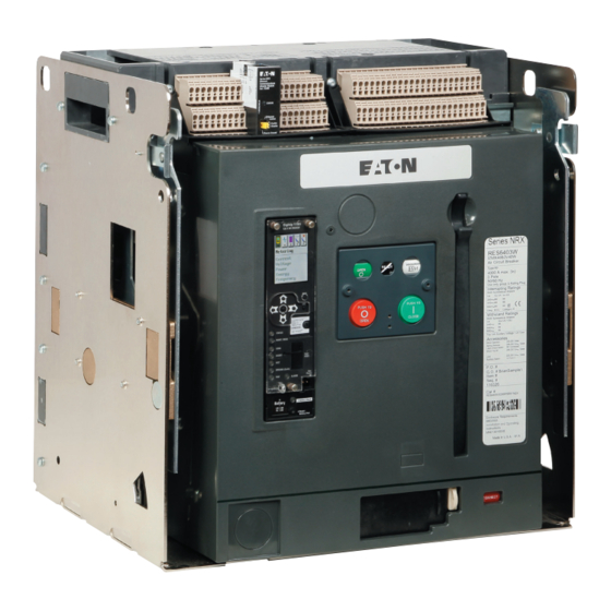
SPARE PARTS IN THE REPAIR OF THE EQUIPMENT. THE SPECIFIED MAINTENANCE INTERVALS AS WELL AS THE INSTRUCTIONS FOR REPAIR Mounting AND EXCHANGE MUST BE STRICTLY ADHERED TO PREVENT INJURY TO feet for fixed mounting PERSONNEL AND DAMAGE TO THE EQUIPMENT. Shroud Figure 1. Front connect breaker EATON www.eaton.com... - Page 3 Standard Cu/Al pressure terminals TA700NB1M Aluminum Cu/Al 1–500 kcmil (2) 50–240 TA700NB1MCWT TA1000NB1M 1000 Aluminum Cu/Al 3/0–400 kcmil (3) 95–185 TA1000NB1MCWT TA1200NB1M 1200 Aluminum Cu/Al 4/0–500 kcmil (4) 120–240 TA1200NB1MCWT TA1201NB1M 1201 Aluminum Cu/Al 500–750 kcmil (3) TA1201NB1MCWT TA1201NB1 TA1201NB1CWT EATON www.eaton.com...
- Page 4 Step 2 Secondary Terminal contact block With the screws removed, pull out the front of the arc hood and set shield assembly it aside (Figure 4) . Front terminal load shield Figure 6. Step 4 Figure 4. Step 2 EATON www.eaton.com...
- Page 5 . m CAUTION Figure 7. Step 5 MAKE SURE THE PHASE BARRIERS FROM STEP 6.5 ARE PROPERLY INSTALLED BEFORE PLACING THE CIRCUIT BREAKER INTO SERVICE. FAILURE TO FOLLOW THESE REQUIREMENTS COULD RESULT IN EQUIPMENT DAMAGE AND/OR FAILURE. EATON www.eaton.com...
- Page 6 Type NF bus extension kit for 65 kA Effective February 2016 fixed front connect breaker Figure 8. Assembly view (refer to only the line side for this kit) Figure 9. Assembly view (refer to only the line side for this kit) EATON www.eaton.com...
- Page 7 Figure 11. Cable terminal kit otee: Terminals sold separately . NOTICE TA1201NB1 (M) [3] 500 – 750 (300) CU/AL (42) 66B2638H01 Figure 14. Step 7.2—Cable terminals connected onto bus extensions on both line and load side Figure 12. Cable terminals torque requirements EATON www.eaton.com...
-
Page 8: Disclaimer Of Warranties And Limitation Of Liability
ANY CONTRACT BETWEEN THE PARTIES . in Figure having a minimum tensile strength of 2000 pounds at In no event will Eaton be responsible to the purchaser or user in 6 inches from terminals and every contract, in tort (including negligence), strict liability or otherwise...
Need help?
Do you have a question about the NRX Series and is the answer not in the manual?
Questions and answers