Table of Contents
Advertisement
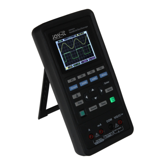
JT-DMSO2D72
Portable 3-in-one oscilloscope, signal generator and multimeter
1. GENERAL INFORMATION
Dear customer,
Thank you for choosing our product. Please read the following im-
portant information before putting the device into operation.
This oscilloscope is compact, portable and flexible. It has a TFT-LCD
color display with a resolution of 320 x 240 pixels and adjustable
backlight brightness.
The maximum real time sampling rate can be up to 250 MSa/s. USB
memory devices are also supported, the user can upgrade the firm-
ware via USB, the edge trigger function is automatically detected and
it has a user-defined fast offset calibration with A/D converter that
can sample each channel simultaneously.
3
Advertisement
Table of Contents

Related Manuals for Joy-it JT-DMSO2D72


Summary of Contents for Joy-it JT-DMSO2D72
- Page 1 JT-DMSO2D72 Portable 3-in-one oscilloscope, signal generator and multimeter 1. GENERAL INFORMATION Dear customer, Thank you for choosing our product. Please read the following im- portant information before putting the device into operation. This oscilloscope is compact, portable and flexible. It has a TFT-LCD color display with a resolution of 320 x 240 pixels and adjustable backlight brightness.
-
Page 2: Safety Instructions
2. SAFETY INSTRUCTIONS Safety Terms and Symbols: following terms may appear on product: Danger It represents that harms may be caused to you at once if you per- form the operation. Warning It represents that latent harms may be caused to you if you per- form the operation. -
Page 3: Technical Specifications
Connect the probe the right way. The probe ground lead is at ground po- tential. Do not connect the ground lead to an elevated voltage. Check all terminal ratings. To avoid fire or shock hazard, check all ratings and markings on the product. Refer to the product manual for detailed in- formation about ratings before making connections to the product. - Page 4 Selectable analog bandwidth limit, Typical 20 MHz (reduced to 6 MHz when typical using a 1x probe) Low frequency response (-3db) ≤ 10 Hz DC gain accuracy 10V/div - 10mV/div ±3% for normal or Trigger Type Edge Mode Auto, Normal, Single Level ±...
- Page 5 Allowed relative humidity ≤ 40°C: ≤90% RH, 40-50°C: ≤60% RH Cooling Method Convection Altitude: -Operating and Nonoperating 3 000 m (10 000 feet) -Random vibration 0.31 g from 50 - 500Hz, 10 minutes on each axis -Nonoperating 2,46 g from 5 - 500 Hz, 10 minutes on each axis Mechanical shock in operation 50 g, 11 ms, half sine...
- Page 6 Range Accuracy Resolution 400.00mV 100uV 4.000V ±(0.8% + 5) 40.00V 10mV 400.0V 100mV DC Voltage 600.0V ±(1% + 2) Overload protection: 400mV: 250V, other: 600Vrms. 4.000V 40.00V 10mV ±(1.2% + 5) 400.0V 100mV AC Voltage 600.0V ±(1.5% + 5) Frequency: 40Hz~400Hz; Frequency of 400V and 600V: 40Hz~100Hz 40.00mA 10uA...
-
Page 7: Getting Started
All specifications herein mentioned apply to the series oscilloscopes. Before checking an oscilloscope to see if it complies with these specifications, make sure it meets the following conditions: The oscilloscope must have been operating continuously for twenty minutes un- der the specified operating temperature. The Do Self Cal operation must be performed through the Utility menu if the oper- ating temperature changes by more than 5°C. - Page 8 Adjust the bracket When using the instrument, you can open the support foot to tilt the instrument upward for easy operation and observation. When the instrument is not in use, the user can close the support foot to facilitate placement or han- dling.
- Page 9 The user interface • Functional Check • Follow the steps below to perform a quick functional check to your oscilloscope. Power Press the power key and the device starts. Press the power key again, and the de- vice will shut down. Before starting it, please confirm that the battery has enough power.
-
Page 10: Probe Check
3. Press the Auto button and you should see within a few seconds a square wave of about 2V peak-to-peak at 1KHz in the display. Repeat the steps to observe CH2. Probe check • Safety When using the probe, keep your fingers behind the guard on the probe body to avoid electric shock. -
Page 11: Function Introduction
You can press Channel button to enter the channel setting menu and select CH1, and select the Probe option that matches the attenuation factor of your probe. Make sure that the Attenuation switch on the probe matches the Probe option in the oscillo- scope. - Page 12 F1/F2/F3/F4: Multi function key, in each menu mode, is responsible for selecting corresponding menu items in the screen. Shortcut keys. Long press this button to enter the menu, and choose shortcut key function; After setting, press this button sin- gle time to respond to the corresponding function. In scope, stop or run the waveform acquisition;...
- Page 13 Automatic set • Auto set is one of the advantages digital oscilloscopes have. When you push the Auto button, the oscilloscope will identify the type of waveform (sine or square wave) and adjust controls according to input signals so that it can accurately display the wave- form of the input signal.
-
Page 14: Horizontal System
Long press button, to enter Short key setting menu, and select Default. Press button, pops up the prompt to recall the default settings on the screen, now press F1 to confirm. The oscilloscope will display the CH1 waveform and remove all the others. - Page 15 Vertical System Vertical system can be used to adjust the vertical scale and location and other set- tings of the channel. Each channel has a separate vertical menu, and each channel can be set separately. 1.Vertical Position Press Channel->F1 to select the channel, and press Up or Down direction keys to move the vertical position of the selected channel.
- Page 16 Slope: Select the trigger slope to rising, falling, rising & falling. Trigger Mode: You can select the Auto or Normal mode to define how the oscil- loscope acquires data when it does not detect a trigger condition. Auto Mode per- forms the acquisition freely in absence of valid trigger.
-
Page 17: Reference Waveform
Reference Waveform The REF channel is used to display the reference waveform, which can compare the actual waveforms with the reference waveforms to find out the differences. Press Menu button to enter, and select Ref to enter reference Waveform menu. REF Menu Table: Menu Setting... - Page 18 To do cursor measurement, follow these steps: 1. Press F1 to open the cursor measurement; 2. Press F2 to select a type of cursor measurement. 3. Press F3 to select the channel that needs to be measured. 4. Press F4 to enter the second page, press F1 or F2 to select Cursor1 or Cursor2, press up, down, left and right to move Cursor1 or Cursor1;...
-
Page 19: Digital Multimeter
Note: 1. Backlight time and automatic shutdown time will not be executed when the os- cilloscope is plugged in with an external charging device or connected to a comput- er via a USB cable. 2. Shutdown automatically saves last setup. Self calibration The self calibration routine helps optimize the oscilloscope signal path for maxi- mum measurement accuracy. - Page 20 Measurement 1. DC and AC voltage measurement Press the power button to turn on, then press the "DMM" button to enter to the multi meter function interface; Press the up, down, left and right direction keys or F1, F2, F3, F4 multi-function keys to select "DC V", "DC mV"...
-
Page 21: Signal Generator
Connect the red and black forms to the measured point. The diode value of the mea- sured point will be displayed on the screen. 6. Buzzer measurement Press the power button to turn on, then press the "DMM" button to enter to the multi meter function interface;... - Page 22 4. Set offset Press F4 button to enter the second page. Press F2 to select Offset, then use the up, down, left and right direction keys to adjust the frequency, press F2 button to open the digital keyboard again, use the up, down, left, right direction keys and "Enter" key to set frequency parameter, select "OK"...
- Page 23 1. Install the software Download the latest software on the official website, double click Setup.exe to install. The link is as follows: https://joy-it.net/files/files/Produkte/JT-DMSO2D72/DMSO2D72_Software.zip 2. Install the driver Connect the oscilloscope to the computer via the USB cable. Open the device manager of the computer and find the device.
- Page 24 3.Double-click the Hantek2xx2 icon to open the software and select "DDS" in the right control bar to enter the signal generator control bar. 4. Put "√" in the box in front of "on/off" to open the signal output. 5. Select "signal type" as "arb", and set the corresponding frequency and amplitude. 6.
- Page 25 8. CHARGE When the battery on the screen is displayed as blank, it indicates that the battery is about to run out. When the battery power is too low, the oscilloscope will prompt “Power off after 5s”. In order to avoid the automatic shutdown of the oscilloscope due to insufficient power supply, please charge it in time.
-
Page 26: Troubleshooting
In addition, you may press the Auto button to perform an automatic detection of signals at first. Contact Joy-IT Technical Support department in time if there is still no display of waveforms. 3. If the waveform of the input signal is distorted seriously, follow these steps: Check the probe to assure its proper connection to the channel BNC. -
Page 27: General Care And Cleaning
10. GENERAL CARE AND CLEANING General Care Do not put or leave the device in a place where the LCD display will be exposed to direct sunlight for long periods of time. Note: To avoid damage to the oscilloscope or probes, do not expose them to sprays, liquids, or solvents. -
Page 28: Product Recycling
Possibility of return in your area: We will send you a parcel stamp with which you can return the device to us free of charge. Please contact us by e-mail at Service@joy-it.net or by telephone. Information on packaging: Please pack your old appliance safely for transport, if you do not have suitable packaging material or do not wish to use your own, please contact us and we will send you suitable packaging.
Need help?
Do you have a question about the JT-DMSO2D72 and is the answer not in the manual?
Questions and answers