Table of Contents
Advertisement
. . . . . . . . . . . . . . . . . . . . . . . . . . . . . . . . . . . . . .
. . . . . . . . . . . . . . . . . . . . . . . . . . . . . . . . . . . . .
. . . . . . . . . . . . . . . . . . . . . . . . . . . . . . . . .
. . . . . . . . . . . . . . . . . . . . . . . . . . . . . . . . . . . . . . . . . .
. . . . . . . . . . . . . . . . . . . . . . . . . . . . . . . . . . .
. . . . . . . . . . . . . . . . . . . . . . . . . . . . . . . . .
. . . . . . . . . . . . . . . . . . . . . . . . . . . . . . . . . . . . . . . 11
. . . . . . . . . . . . . . . . . . . . . . . . . . . . . . . . . . . . . . 11
. . . . . . . . . . . . . . . . . . . . . . . . . . . . . . . . . 18
. . . . . . . . . . . . . . . . . . . . . . . . . . . . . . . . . . . . . . . 30
. . . . . . . . . . . . . . . . . . . . . . . . . . . . . . . . . . . . . . . . . . . . 34
. . . . . . . . . . . . . . . . . . . . . . . . . . . . . . . . . . . . . . . . . . . . 35
. . . . . . . . . . . . . . . . . . . . . . . . . . . . . . . . . . . . . . . . . . . . . . . 36
© 2020 Roland Corporation
. . . . . . . . . . . . . . . . . .
. . . . . . . . . . . . . . . . . . . . . . . . . . . . . . .
. . . . . . . . . . . . . . . . . . . . . . . . . . .
. . . . . . . . . . . . . . . . . . . .
. . . . . . . . . . . . . . . . . . . . . . . . 10
. . . . . . . . . . . . . . . . . . . 10
. . . . . . . . . . . . . . . . . . . . . . 17
. . . . . . . . . . 19
. . . . . . . . . 22
. . . . . . . . . . . . . . . . . . . . . . . . . . . . . . . 26
. . . . . . . . . . . . . . . . . . . . . . . . . . . . . 28
. . . . . . . . 29
. . . . . . . . . . . . . . . . . . . . . . . . . . . . . . . 30
. . . . . . . . . . . . . . . . . . . . . . . . . . . 31
. . . . . . . . . . . . . . . . . . . . . . . . . 32
. . . . . . . . . . . . . . . . . . . . . . 33
. . . . . . . . . . . . . . . . . . . . . 35
. . . . . . . . . . . . . . . 36
. . . . . . . . . . 37
2
. . . . . . . . . . . . . . . . . . . . . . . . . . . . . . . . . . . . . . . . . . 38
2
4
6
7
7
8
8
9
. . . . . . . . . . . . . . . . . . . . . . . . . . . . . . . . . . . . . . . . . . . 44
9
. . . . . . . . . . . . . . . . . . . . . . . . . . . . . . . . . . . . . . . . . . . . . . . . 46
. . . . . . . . . . . . . . . . . . . . . . . . . . . . . . . . . . . . . . . . . . . 46
. . . . . . . . . . . . . . . . . . . . . . . . . . . . . . . . . . . . . . . . . 47
. . . . . . . . . . . . . . . . . . . . . . . . . . . . . . . . . . . . . . . . . . . . . . 48
. . . . . . . . . . . . . . . . . . . . . . . . . . . . . . . . . . . . . . . . . . . . . . 49
. . . . . . . . . . . . . . . . . . . . . . . . . . . . . . . . . . . . . . . . . . . . . . . . . . . . 53
. . . . . . . . . . . . . . . . . . . . . . . . . . . . . . . . . . . . . . . . . . . . . . . . . . . . 56
. . . . . . . . . . . . . . . . . . . . . . . . . . . . . . . . . . . . . . . . . . . 57
. . . . . . . . . . . . . . . . . . . . . . . . . . . . . . . . . . . . . . . . . . 61
. . . . . . . . . . . . . . . . . . . . . . . . . . . . . . . . . . . . . . . . . . . . . . . 62
. . . . . . . . . . . . . . . . . . . . . . . . . . . . . . . . . . . . . . . . . . . . . . 65
. . . . . . . . . . . . . . . . . . . . . . . . . . . . . . . . . . . . . . . . . 66
. . . . . . . . . . . . . . . . . . . . . . . . . . . . . . . . . . . . . . . . . . . . . . . 67
. . . . . . . . . . . . . . . . . . . . . . . . . . . . . . . . . . . . . . . . . . . . . . . . 71
. . . . . . . . . . . . . . . . . . . . . . . . . . . . . . . . . . . . . . . . . . 71
. . . . . . . . . . . . . . . . . . . . . . . . . . . . . . . . . . . . . . . . . . . . . . 74
Reference Manual
. . . . . . . . . . . . . . . . 38
. . . . . . . . . . . . 39
. . . . . . . . . . . . . . . . . . . . . . . . . . . . . . 40
. . . . . . . . . . . . . . . . . . . . . . . . . . . . . . . . . . . . . . . 41
. . . . . . . . . . . . . . . . . . . . . . . . . . . . . . . . 42
. . . . . . . . . . . . 44
. . . . . . . . . . . . . . . . . . . . . . . . . . . . . . . . . . . . . . 48
. . . . . . . . . . . . . . . . . . . . . . . . . . . . . . . . . . . . . . . . 59
. . . . . . . . . . . . . . . . . . . . . . . . . . . . . . . . . . . . . . . 60
. . . . . . . . . . . . . . . . . . . . . . . . . . . . . . . . . . . . . . 61
. . . . . . . . . . . . . . . . . . . . . . . . . . . . . . . . . . . . . 63
. . . . . . . . . . . . . . . . . . . . . . . . . . . . . . . . . . . . . . 70
. . . . . . . . . . . . . . . . . . . . . . . . . . . . . . . . . . . . . . . 72
. . . . . . . . . . . . . . . . . . . . . . . . . . . . . . . . . . . . . 75
. . . . . . . . . . . . . . . . . . . . . . . . . . . . . . . 90
. . . . . . . . . . . . . . . . . . . . . . . . . . . . . . . . . . . . . 91
. . . . . . . . . . . . . . . . . . . . . . . . . . . . . . . . . . . . . 92
. . . . . . . . 43
. . . . . . . . . . 45
02
Advertisement
Table of Contents

Subscribe to Our Youtube Channel
Related Manuals for Roland V-8HD


Summary of Contents for Roland V-8HD
-
Page 1: Table Of Contents
. . . . . . . . . . . . . . . . . . . . . . . . . . . . . . . . . . . from the V-8HD . -
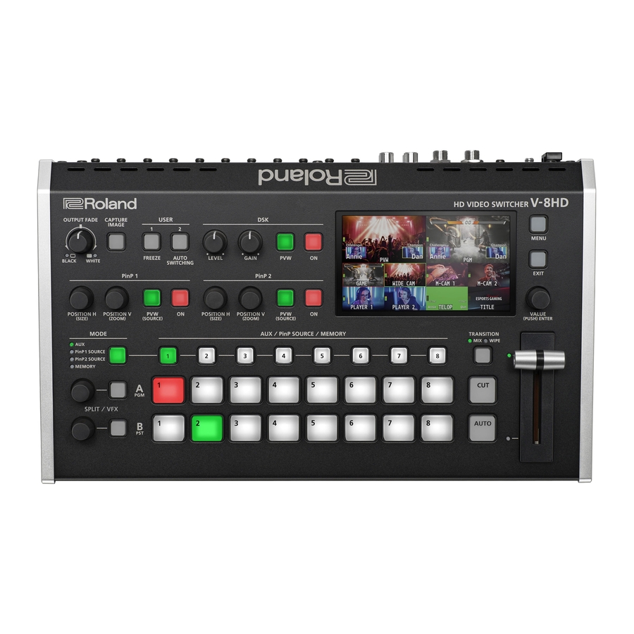
Page 2: Panel Descriptions
Panel Descriptions Top Panel / Side Panel Name Explanation Name Explanation The program output video and audio fade in/out. PinP 1 Turning the knob toward the left fades the During PinP 1 compositing, this adjusts the output to black, and turning the knob toward the [POSITION H] knob horizontal display position of the inset screen. - Page 3 Panel Descriptions Name Explanation Name Explanation Selects the video transition effects. AUX / PinP SOURCE / MEMORY The two pictures are blended Select the object of operation according to the [TRANSITION] together as the video is switched. function selected by the [MODE] button. button The original video is broken into by WIPE...
-
Page 4: Rear Panel (Connecting Your Equipment)
* Never turn off the power or remove an HDMI output connector. the USB flash drive while the USB he V-8HD menu is shown on the display that’s flash drive is being accessed. connected to the OUTPUT 3 connector. - Page 5 Panel Descriptions Connecting a Footswitch CTL/EXP 2 CTL/EXP 1 FS-5U x 2 FS-5U x 1 FS-6 FS-7 Stereo 1/4” phone type 1/4” phone type Stereo 1/4” phone type Stereo 1/4” phone type 1/4” phone type x 2 1/4” phone type Stereo 1/4”...
-
Page 6: Multi-View Monitor Display
5 You can edit the label name. Use the SYSTEM menu item “MULTI-VIEW LABEL EDIT” to edit the label name. 5 For details on the cameras that support the REC indicator function, refer to the Roland website. https://proav .roland .com... -
Page 7: Turning The Power On/Off
About the Auto Off function 5 Pressing the [EXIT] button moves you back one level higher. The power to the V-8HD turns off automatically when all of the following states persist for 240 minutes (Auto Off function). Turn the [VALUE] knob to change the value of the 5 No operation performed on the V-8HD setting. -
Page 8: Video Input/Output Settings
Setting the System Format Setting the Input Formats for Channels 7 and 8 On the V-8HD, the input/output format is determined according to By factory default, the EDID assignment for channels 7 and 8 is the system format. You set the input/output format to match the “INTERNAL”... -
Page 9: Adjusting Output Video
Here’s how to adjust the output image appropriately for the device Here’s how to adjust the character of the video that’s input to INPUT that’s receiving the V-8HD’s output. 1–8. For INPUT 7 and 8 connectors, you can also adjust the scaling. -
Page 10: Changing Output Bus Assignments
Video Input/Output Settings Changing Output Bus Assignments Inputting Copy-Protected (HDCP) Video The V-8HD has four internal output buses (PROGRAM, PREVIEW, AUX, If you want to input HDCP-protected video from a BD player or other and MULTI-VIEW). device, you can enable HDCP input. -
Page 11: Video Operations
Video Operations Switching the Video Here’s how to switch between input video while applying an effect, and final output. About the operation mode for video transitions Using Mix/Wipe to Switch Video There are two operation modes for switching the video on the When A/B mode PGM/A bus and PST/B bus: the “PGM/PST mode”... - Page 12 Video Operations When PGM/PST mode is selected Changing the mix/wipe pattern You can use the MIX/WIPE menu to specify the pattern by which the Flip the video fader all the way upward or downward. mix/wipe occurs and the direction of the wipe. Press the [MENU] button0select “MIX/WIPE,”...
- Page 13 Video Operations Using the [AUTO] or [CUT] Button to Switch Video You can use the [AUTO] or [CUT] button to switch video, without using the video fader. * You can perform operations using the [AUTO] and [CUT] buttons both in the PGM/PST mode and in the A/B mode. Changing the functions of the [CUT] and [AUTO] buttons Press the [AUTO] or [CUT] button at the desired timing for switching the video.
- Page 14 Video Operations Switching the Video Automatically (Auto Switching) The video of INPUT 1–8 or of preset memories can be switched automatically (the auto switching function). You can make operation easier by letting the video switch automatically. Operation modes for auto switching Specifying the operation mode Auto switching provides three operation modes that you Input scan...
- Page 15 Video Operations Preset memory scan BPM sync Press the [MENU] button0”AUTO SWITCHING”0 Press the [MENU] button0”AUTO SWITCHING”0 select “TYPE, ” and press the [VALUE] knob. select “TYPE, ” and press the [VALUE] knob. Turn the [VALUE] knob to select “PRESET MEMORY Turn the [VALUE] knob to select “BPM SYNC,”...
- Page 16 Video Operations Switching AUX Output You can use button operations to directly select the video to send to the AUX bus. Sending the same video as the PGM output to the Use the [MODE] button to select “AUX.” AUX output By using the AUX link function, you can send the same video as the PGM bus (the final output video) to the AUX bus.
-
Page 17: Compositing Video With Split (Split)
Video Operations Compositing Video with Split (SPLIT) This composites two video streams in a split screen. The final output video is displayed above or on the left, and the preset video (the video to be output next) is displayed below or on the right. Specifying a Split Composition Pattern Compositing Using Split This makes the settings for the split composition pattern to match... -
Page 18: Using A Visual Effect (Vfx)
Video Operations Using a Visual Effect (VFX) Here’s how you can apply an effect to the entire video, such as varying the video’s color or shape. You can apply a visual effect (VFX) to the A/PGM bus and B/PST bus respectively. Selecting a Visual Effect Applying Visual Effects Press the [MENU] button0”SPLIT/VFX”0select... -
Page 19: Compositing Video With Picture-In-Picture (Pinp)
Video Operations Compositing Video with Picture-in-Picture (PinP) Here’s how to composite an inset screen (a small separate screen) Inset screen 1 Inset screen 2 onto the background video. PinP 1 (PinP 1) (PinP 2) You can use PinP 1 and PinP 2 simultaneously to composite two inset screens. - Page 20 Video Operations Making Detailed Settings for the Inset Screen Using Key Compositing to Remove the PinP Background Video Detailed settings for size, shape, and border width etc. can be made for the PinP 1 and PinP 2 inset screens respectively. By changing the PinP type, you can composite the video by applying “luminance key”...
- Page 21 Video Operations Copying the PinP Settings Exchanging the PinP 1 and PinP 2 Settings You can copy the PinP 2 settings to PinP 1, or the settings of PinP 1 to You can exchange the settings of PinP 1 and PinP 2. PinP 2.
-
Page 22: Compositing Video With Downstream Keyer (Dsk)
Video Operations Compositing Video with Downstream Keyer (DSK) Here’s how you can turn a portion of the video transparent and composite it with the background video. You can use luminance key with either a black or a white background, or a chroma key with either a blue or green background. You can additionally composite a variety of text and images with video that was composited using PinP or another method. - Page 23 Video Operations Modifying the superimposed video When using luminance key compositing, you can fill-in the superimposed image or add an edge to it. * This setting is in common with chroma key. Press the [MENU] button0select “DSK,” and press the [VALUE] knob. Turn the [VALUE] knob to select the menu items shown below, and press the [VALUE] knob.
- Page 24 Video Operations Using Chroma Key Compositing using chroma key Chroma key This cuts out a video by turning the blue or green portion transparent, and composites it onto the background video. Using Output the background video. this, you can composite only a subject that you are photographing At the PVW section of the monitor, check the video to be made against a blue screen or green screen.
- Page 25 Video Operations Finely adjusting the key color (removed color) Turn the [VALUE] knob to change the value, and press the [VALUE] knob. Press the [MENU] button0select “DSK,” and press Press the [MENU] button to quit the menu. the [VALUE] knob. To specify a desired color as the key color (sampling marker) You can specify the key color to be made transparent simply by sampling (detecting) a color from the video.
-
Page 26: Using Imported Still Images
Video Operations Using Imported Still Images You can take a still image captured from input/output video or imported from a USB flash drive, assign it to channel 1 or 8, and output it in the same way as video. You can also use it as a source for DSK compositing (p. 22). You can save up to eight still images in the unit. - Page 27 5 When you’re using a USB flash drive for the first time, be sure to and press the [VALUE] knob. format it on the V-8HD (p. 40). 5 Depending on the USB flash drive, recognition of the flash drive might take some time.
-
Page 28: Freezing Input Video (Freeze)
Video Operations Deleting a Still Image Freezing Input Video (Freeze) Here’s how to delete the still image that’s saved in the unit. This temporarily pauses the incoming video. You can apply transition effects and visual effects during a video Press the [MENU] button0”STILL IMAGE”0select freeze. -
Page 29: Applying A Fade To The Output Video (Output Fade)
Video Operations Applying a Fade to the Output Video (Output Fade) You can apply a fade to the output video. This lets you make the main output video fade to a black (or white) picture at times when you want to suppress video output, such as during intervals in a presentation, event or band performance. -
Page 30: Audio Operations
* If the volume level of speaker output is unsuitable even when the volume level on the V-8HD has been adjusted so that level meter light up in yellow, adjust the volume for the speakers and amplifiers. Using “OUTPUT LEVEL” to make adjustments can... -
Page 31: Applying Effects To Input Audio
You can modify the tonal character by applying effects to the audio input. Using an effect preset A confirmation message appears. The V-8HD is equipped with effects that are adjusted for specific environments. These are called “effect presets. ” The effect presets are created using a combination of three effects * If you decide to cancel, press the [EXIT] button. -
Page 32: Applying Effects To Output Audio
Audio Operations Applying Effects to Output Audio You can modify the tonal character by applying effects to the audio output. * You can apply a limiter (LIMITER) to the audio of the AUX bus. LIMITER Press the [MENU] button0”AUDIO OUTPUT”0 select “MASTER OUTPUT”... -
Page 33: Silencing Only Specific Audio (Mute)
Audio Operations Silencing Only Specific Audio (Mute) Here’s how to temporarily silence specific input audio or output audio (the mute function). Muting input audio Muting AUX-bus Audio Press the [MENU] button0”AUDIO INPUT”0select Press the [MENU] button0”AUDIO OUTPUT”0 “INPUT 1”–“INPUT 8” or “AUDIO IN,” and press the ”AUX”0select “AUX MUTE,”... -
Page 34: Interlinking Audio Output To Video Switching (Audio Follow)
Audio Operations Interlinking Audio Output to Video Switching (Audio Follow) You can associate audio with a video switch so that when the video is switched, the specified audio alone is output automatically, and other audio is automatically muted. Applying audio follow to the audio from AUDIO IN Follow the procedure in “Adjusting the Volume Level”... -
Page 35: Checking A Specific Audio Input (Solo)
Audio Operations Checking a Specific Audio Input (Solo) Switching the Audio That’s Output from the AUDIO OUT and PHONES Jacks Here’s how you can temporarily monitor a specific audio input via the headphones (solo function). Here’s how to switch the audio that is output from the AUDIO OUT * The solo function applies to the headphone output. -
Page 36: Switching The Audio That's Output From The Output 1-3 Connectors
Audio Operations Switching the Audio That’s Output from Sending the AUDIO IN Audio to the AUX Bus the OUTPUT 1–3 Connectors You can send the input audio of the AUDIO IN jacks to the AUX bus. Here’s how to switch the audio that is output from the OUTPUT 1–3 Press the [MENU] button0“AUDIO OUTPUT”0 connectors. -
Page 37: Specifying The Type Of Audio Sent To The Aux Bus
Audio Operations Specifying the Type of Audio Sent to the AUX Bus When sending audio from INPUT 1–8 and AUDIO IN to the AUX bus, you can specify whether to send the audio as-is or with an effect applied. Press the [MENU] button0“AUDIO OUTPUT”0 select “AUX,”... -
Page 38: Other Features
About the last memory function The V-8HD has a built-in Last Memory function. Last Memory is a function that saves the state of the unit that is in effect immediately before power-down, and automatically restores the state at the next startup. The Last Memory function is enabled by default. If you want the unit to recall a specific preset memory when it starts up, use the PRESET MEMORY menu item “START UP”... -
Page 39: Saving The Unit's Settings On A Usb Flash Drive
You can access the saved file (*.V08) on the USB flash drive and load it into the unit for use when needed. * When you’re using a USB flash drive for the first time, be sure to format it on the V-8HD (p. 40). -
Page 40: Formatting Usb Flash Drives
Loading settings overwrites the preset memory on the unit. the V-8HD. NOTE Press the [MENU] button0“USB MEMORY”0 5 The V-8HD does not recognize unformatted USB flash drives. select “RESTORE ALL SETTINGS,” and press the 5 Performing formatting causes all data already saved on the USB [VALUE] knob. -
Page 41: Using A Footswitch
Other Features Using a Footswitch You can use a footswitch connected to the CTL/EXP 1, 2 jacks of the V-8HD to control the V-8HD with your foot. You can assign various functions to the footswitch. Connect a footswitch as described in p. 5. -
Page 42: Using An Expression Pedal
Other Features Using an Expression Pedal You can use an expression pedal connected to the CTL/EXP 1, 2 jacks of the V-8HD to control the V-8HD with your foot. Adjusting the pedal (pedal calibration) MEMO You should normally use the EV-5 with its minimum volume knob The first time you use an expression pedal, you must calibrate (adjust) left in the zero position. -
Page 43: Assigning The Functions Of The User [1] [2] Buttons
Other Features Assigning the Functions of the USER [1] Value Explanation No function is assigned. [2] Buttons Slides the video fader to the top edge or VIDEO FADER bottom edge. Switches the video between A/PGM bus and * With the factory settings, the freeze function is assigned to the H CUT I B/PST bus as a cut. -
Page 44: Preventing Unintended Operation (Panel Lock)
If a recorder that supports the “HDMI REC TRIGGER” function is unintended operation. connected to an OUTPUT of the V-8HD, you can use the USER [1] or [2] button of the V-8HD to control video record start/stop on that recorder. -
Page 45: Returning To The Factory Settings (Factory Reset)
Returning to the Factory Settings (Factory Reset) Here’s how you can return the settings of the V-8HD to their factory- set state. If following the procedures described in this manual does not cause the result you expect, try executing a factory reset. -
Page 46: Menu List
FWXGA (1366x768) What is EDID? SXGA (1280x1024) EDID EDID is data that is transmitted from the V-8HD to the source device when the SXGA+(1400x1050) V-8HD is connected to a source device. EDID contains data such as the formats UXGA (1600x1200) -
Page 47: 2: Video Output
-64–0–63 Adjusts the green level. BLUE -64–0–63 Adjusts the blue level. Specifies whether video record start/stop on a recorder equipped with the REC CONTROL OFF, HDMI REC TRIGGER function will (ON) or will not (OFF) be controlled from the V-8HD. -
Page 48: 3: Transition Time
Menu List 3: TRANSITION TIME Menu item Value Explanation (Bold: default) MIX/WIPE TIME 0.0–1.0–4.0sec Specifies the video transition time. PinP 1 TIME 0.0–1.0–4.0sec Specifies the fade time with which the PinP 1 or PinP 2 inset screen appears or disappears when using Picture in Picture (PinP) compositing. PinP 2 TIME 0.0–1.0–4.0sec Specifies the fade time with which the superimposed logo or video appears or... -
Page 49: 5: Split/Vfx
Menu List 5: SPLIT/VFX SPLIT/VFX A, B Menu item Value Explanation (Bold: default) Turns the split/visual effect on/off. SPLIT/VFX OFF, ON You can also use the SPLIT/VFX [A] or [B] button to turn this on/off. SPLIT V, SPLIT H, PART MOSAIC, BACKGROUND MOSAIC, FULL MOSAIC, WAVE, RGB REPLACE, COLORPASS,... - Page 50 Menu List 9 SPLIT/VFX TYPE: BACKGROUND MOSAIC Applies a mosaic to the portion of the selected area. Menu item Value Explanation (Bold: default) Adjusts the horizontal position of the selected area. POSITION H -100.0–0.0–100.0% You can adjust this by turning the SPLIT/VFX [A] or [B] knob. Adjusts the vertical position of the selected area.
- Page 51 Menu List 9 SPLIT/VFX TYPE: COLORIZE Adds color to the video. Menu item Value Explanation (Bold: default) TYPE Specifies the type of colorize. 1–8 MIX LEVEL Adjusts the intensity (output level) of the video with the visual effect applied. 0–255 9 SPLIT/VFX TYPE: POSTERIZE Changes the gradations in brightness.
- Page 52 Menu List 9 SPLIT/VFX TYPE: SATURATION OFFSET Changes the visual character by controlling the saturation. Menu item Value Explanation (Bold: default) VALUE Specifies the reference value for saturation. -256–0–255 MIX LEVEL 0–255 Adjusts the intensity (output level) of the video with the visual effect applied. 9 SPLIT/VFX TYPE: VALUE OFFSET Changes the visual character by controlling the brightness.
-
Page 53: 6: Pinp
Menu List 6: PinP PinP 1, 2 Menu item Value Explanation (Bold: default) Specifies the video source of the inset screen. PinP SOURCE HDMI 1–8, STILL 1–8 If MODE is “PinP 1 SOURCE” or “PinP 2 SOURCE, ” you can also use the PinP SOURCE [1]–[8] buttons to switch this. - Page 54 Menu List Menu item Value Explanation (Bold: default) KEY LEVEL 0–64–255 Adjusts the degree of extraction (transparency) for the key. KEY GAIN 0–255 Adjusts the degree of edge blur (semi-transmissive region) for the key. MIX LEVEL 0–255 Adjusts the key’s overall density (output level). If this is “MATTE, ”...
- Page 55 Menu List 9 PinP TYPE: CHROMA KEY Composites the video by applying chroma key to the PinP. Menu item Value Explanation (Bold: default) COPY SETTINGS FROM EXEC Copies the another PinP settings. PinP 2 (or PinP 1) SWAP SETTINGS FROM EXEC Exchanges the settings of PinP 1 and PinP 2.
-
Page 56: 7: Dsk
Menu List 7: DSK Menu item Value Explanation (Bold: default) DSK SOURCE HDMI 1–8, STILL 1–8 Select the source of the logo or image that you want to superimpose. Specifies the DSK type used during DSK composition. Composite using luminance key. LUMINANCE-WHITE Makes white portions transparent according to brightness. -
Page 57: 8: Audio Input
Menu List 8: AUDIO INPUT INPUT1–8, AUDIO INPUT Menu item Value Explanation (Bold: default) INPUT LEVEL -INF–0.0–10.0dB Adjusts the input volume. Turns the mute function on/off. If this is “ON, ” the input audio is temporarily OFF, ON INPUT MUTE silenced. - Page 58 Menu List Menu item Value Explanation (Bold: default) Turns the equalizer on/off. EQUALIZER OFF, ON Effect Adjusts the tone for each frequency band. Hi GAIN -15.0–0.0–15.0dB Boosts or attenuates the high band. Hi FREQUENCY 1.0–10.0–20.0kHz Specifies the center frequency when changing the tone in the high band. Mid GAIN -15.0–0.0–15.0dB Boosts or attenuates the middle band.
-
Page 59: 9: Audio Output
Menu List 9: AUDIO OUTPUT OUTPUT ASSIGN Menu item Value Explanation (Bold: default) Specifies the audio bus assigned to the AUDIO OUT jacks. MASTER OUTPUT AUDIO OUT Output the audio of the MAIN bus. Output the audio of the AUX bus. Specifies the audio bus assigned to the PHONES jack. -
Page 60: 10: Audio Follow
Menu List Menu item Value Explanation (Bold: default) 1.00: 1, 1.12: 1, 1.25: 1, 1.40: 1, 1.60: 1, 1.80: 1, 2.00: 1, 2.50: 1, Specifies the amount of compression applied in the low band. Lo RATIO 3.20: 1, 4.00: 1, 5.60: 1, 8.00: 1, The state in which no compression is applied is defined as “1. -
Page 61: 11: Preset Memory
Menu List 11: PRESET MEMORY Menu item Value Explanation (Bold: default) Selects the preset memory to load. LOAD MEMORY 1–8 Pressing the [VALUE] knob lets you load the preset memory. Selects a preset memory for saving settings. Pressing the [VALUE] knob lets you save the settings to the preset memory. * The state of the [PHONES] knob (headphone volume) is not saved in preset memory. -
Page 62: 13: Freeze
Menu List 13: FREEZE Menu item Value Explanation (Bold: default) Turns the freeze function on/off. If this is “ON, ” the input video is temporarily frozen. FREEZE OFF, ON If “FREEZE” is assigned to the USER [1] or [2] button, you can also switch this by pressing the button. -
Page 63: 14: Auto Switching
Menu List 14: AUTO SWITCHING Menu item Value Explanation (Bold: default) Turns the auto switching function on/off. If this is “ON, ” the INPUT 1–8 video or preset memory are switched OFF, ON AUTO SWITCHING automatically. If “AUTO SWITCHING” is assigned to the USER [1] or [2] button, you can also switch this by pressing the button. - Page 64 Menu List 9 TYPE: BPM SYNC This automatically switches the video at specified BPM intervals. Menu item Value Explanation (Bold: default) 20–120–250 Specifies the BPM. Specifies how the picture is switched. TRANSITION MODE The picture switches using the currently selected transition effect (mix or wipe). The picture switches instantly.
-
Page 65: 15: Ctl/Exp
Menu List 15: CTL/EXP CTL/EXP 1, 2 Value Menu item Explanation (Bold: default) Specifies the device (footswitch, expression pedal) that is connected to the CTL/EXP jack. Disables the CTL/EXP jack. CTL/EXP TYPE CTL A & CTL B Choose this if a footswitch is connected. Choose this if an expression pedal is connected. -
Page 66: 16: Usb Memory
Menu List Menu item Value Explanation (Bold: default) Consecutively switches the input video in the order of INPUT 108 each time INPUT SCAN NORMAL you press. Consecutively switches the input video in the order of INPUT 801 each time INPUT SCAN REVERSE you press. -
Page 67: 17: System
FRAME RATE 59.94, 50, 60Hz * When you change the setting, the change is not applied until you press the [VALUE] knob to confirm. Specifies the system format for the V-8HD. SYSTEM FORMAT 1080p 720p, 1080i, * When you change the setting, the change is not applied until you press the [VALUE] knob to confirm. - Page 68 Menu List Menu item Value Explanation (Bold: default) Specifies whether the same video as the PGM bus is sent to the AUX bus (AUX link). Use the AUX [1]–[8] buttons to select the video of the AUX bus. AUX link is enabled, and the same video as the PGM bus is sent to the AUX bus. Temporarily disabling AUX link When you press an AUX [1]–[8] button, the selection of the AUX [1]–[8] button AUX LINKED PGM...
- Page 69 If this is “ON, ” and the video that is being output as the program disappears, the program automatically switches to another input video. Turns the Auto Off function on/off. If this is “ON, ” the power to the V-8HD turns off automatically when all of the following states persist for 240 minutes. AUTO OFF...
-
Page 70: List Of Shortcut Keys
Menu List List of Shortcut Keys You can set the following items without showing a menu. Menu item Operation Remarks MIX/WIPE MIX TYPE Hold down the [TRANSITION] button and turn the SPLIT/VFX [A] knob TRANSITION TYPE: MIX WIPE TYPE Hold down the [TRANSITION] button and turn the SPLIT/VFX [A] knob WIPE DIRECTION Hold down the [TRANSITION] button and turn the SPLIT/VFX [B] knob Hold down the [TRANSITION] button and turn the SPLIT/VFX [A] knob while... -
Page 71: Appendix
Appendix Troubleshooting If you suspect a malfunction, please check the following points. If this does not resolve the problem, contact a nearby Roland Service Center. Problem Items to check Action Page Video-related problems Video in a format that differs from the setting on the V-8HD is Could an AUX/PinP SOURCE/MEMORY [1]–[8] button... -
Page 72: Main Specifications
Appendix Main Specifications Roland V-8HD: HD Video Switcher 9 Video Video Processing 4:2:2 (Y/Pb/Pr), 8-bit HDMI type A x 6 INPUT 1–6 * HDCP supported Input Connectors HDMI type A x 2 INPUT 7–8 * HDCP supported * Multi-format supported... - Page 73 4 lbs 7 oz Startup Guide Accessories AC adaptor Power cord * 0 dBu = 0.775 Vrms * This document explains the specifications of the product at the time that the document was issued. For the latest information, refer to the Roland website.
-
Page 74: Dimensions
Appendix Dimensions Unit: mm... -
Page 75: Midi Implementation
Appendix MIDI Implementation 6 General Purpose Controllers 3 (Controller Number 18) Model: V-8HD Date: January 28. 2020 This control the value of PinP 1 POSITION V. Version: 1.03 Status 2nd Byte 3rd Byte Symbol Item Setting Range vv = 0AH–64H (-50–50%) - Page 76 Appendix 6 Undefined (Controller Number 28) 6 Channel volume (Controller Number 39) This control the value of DSK GAIN. This control the value of AUDIO INPUT LEVEL (INPUT 4). Status 2nd Byte 3rd Byte Status 2nd Byte 3rd Byte vv = 00H–7FH (Converted to 0–255) vv = 00H–7FH (refer to “Control Value–Input/Output Level Correspondence Table”...
- Page 77 Appendix 6 Undefined (Controller Number 56) 9 Control Value–Input/Output Level Correspondence Table (unit: dB) This control the value of AUDIO INPUT MUTE (INPUT 1). -Inf -33.1 -11.3 -0.3 Status 2nd Byte 3rd Byte -80.0 -32.3 -10.7 -76.7 -31.5 -10.3 vv = 00H, 01H (OFF, ON) -73.3 -30.8 -10.0...
- Page 78 This is the ID to recognize manufacturer of the exclusive bbH, ccH, ddH, ..., eeH, sum message (manufacturer ID). The manufacturer ID of Roland is 41H. Byte Explanation The ID numbers of 7EH and 7FH are expansion of MIDI standards...
- Page 79 Appendix 2. Parameter Address Map Start Address Description 00H 00H 00H Video Parameter Area 01H 00H 00H Audio Parameter Area 02H 00H 00H System Parameter Area 0AH 00H 00H Other Parameter Area 10H 00H 00H Video Parameter (Memory 1) 11H 00H 00H Audio Parameter (Memory 1) 14H 00H 00H Video Parameter (Memory 2)
- Page 80 Appendix 6 Video Output * “xxH” corresponds to the respective channels as indicated below. xxH: 08H–0AH (OUTPUT 1–3) Address Parameter Name Sys.Ex.Value Meaning of Value 00H xxH 00H OUTPUT ASSIGN 00H–03H PROGRAM, PREVIEW, AUX, MULTI VIEW 00H xxH 01H COLOR SPACE 00H–02H YPbPr, RGB (0–255), RGB (16–235) 00H xxH 02H...
- Page 81 Appendix Address Parameter Name Sys.Ex.Value Meaning of Value 00H xxH 1FH HUE FINE 00H 00H–02H 68H 0–360 00H xxH 21H SATURATION WIDTH 7FH 00H–00H 00H–00H 7FH -128–0–127 00H xxH 23H SATURATION FINE 00H 00H–01H 7FH 0–255 00H xxH 25H FILL TYPE 00H–01H BUS, MATTE 00H xxH 26H...
- Page 82 Appendix Address Parameter Name Sys.Ex.Value Meaning of Value 00H xxH 14H BG MOSAIC AREA SIZE 00H 64H–07H 68H 10.0–100.0% 00H xxH 16H BG MOSAIC AREA CORRECTION H 00H 64H–07H 68H 10.0–100.0% 00H xxH 18H BG MOSAIC AREA CORRECTION V 00H 64H–07H 68H 10.0–100.0% 00H xxH 1AH FULL MOSAIC MODE...
- Page 83 Appendix 7Audio Parameter Area 6 Audio Input * “xxH” corresponds to the respective channels as indicated below. xxH: 00H–08H (INPUT 1–8, AUDIO IN) Address Parameter Name Sys.Ex.Value Meaning of Value 01H xxH 00H 7EH 00H 00H, -INFdB, INPUT LEVEL 7FH 79H 60H–00H 00H 00H– 00H 00H 64H -80.0–0.0–10.0dB 01H xxH 03H INPUT MUTE...
- Page 84 Appendix Address Parameter Name Sys.Ex.Value Meaning of Value 01H 11H 0EH EQUALIZER Mid Q 00H–05H 0.5–16.0 01H 11H 0FH EQUALIZER Lo GAIN 7EH 6AH–00H 00H–01H 16H -15.0–0.0–15.0dB 01H 11H 11H EQUALIZER Lo FREQUENCY 00H–38H 20–500Hz 01H 11H 12H MULTI BAND COMPRESSOR SW 00H–01H OFF, ON 01H 11H 13H...
- Page 85 Appendix 7System Parameter Area 6 Version Address Parameter Name Sys.Ex.Value Meaning of Value 02H 00H 00H System Version Major 00H–09H Version Number (Read Only) 02H 00H 01H System Version Minor (1) 00H–09H Version Number (Read Only) 02H 00H 02H System Version Minor (2) 00H–09H Version Number (Read Only) 6 System...
- Page 86 Appendix Address Parameter Name Sys.Ex.Value Meaning of Value 02H 02H 0BH B/PST 4 SW 00H–01H OFF, ON 02H 02H 0CH B/PST 5 SW 00H–01H OFF, ON 02H 02H 0DH B/PST 6 SW 00H–01H OFF, ON 02H 02H 0EH B/PST 7 SW 00H–01H OFF, ON 02H 02H 0FH...
- Page 87 Appendix 6 AUTO SWITCHING Address Parameter Name Sys.Ex.Value Meaning of Value 02H 05H 00H AUTO SWITCHING SW 00H–01H OFF, ON 02H 05H 01H AUTO SWITCHING TYPE 00H–02H INPUT SCAN, PRESET MEMORY SCAN, BPM SYNC 02H 05H 02H INPUT SCAN SEQUENCE 00H–02H NORMAL, REVERSE, RANDOM 02H 05H 03H...
- Page 88 Appendix 7Other Parameter Area 6 Memory Address Parameter Name Sys.Ex.Value Meaning of Value 0AH 00H 00H Memory Load Trigger 00H–07H Memory 1–8 (Write Only) 0AH 00H 01H Memory Save Trigger 00H–07H Memory 1–8 (Write Only) 0AH 00H 02H Memory Initialize Trigger 00H–07H Memory 1–8 (Write Only) 0AH 00H 03H...
- Page 89 6 2 H 0 3 H 2 3 H 4 3 H 6 3 H Roland Exclusive messages are transmitted with a checksum at the end (before F7) 0 4 H 2 4 H 4 4 H 6 4 H to make sure that the message was correctly received.
-
Page 90: Midi Implementation Chart
MIDI Implementation Chart HD Video Switcher Date: Jan. 28, 2020 Model V-8HD Version: 1.03 Function Transmitted Recognized Remarks Basic Default Channel Changed Default × × Mode Messages × × Altered ************** ************** Note True Voice × × Number Note On ×... -
Page 91: Video Block Diagram
Appendix VIDEO Block Diagram 1080p SYSTEM FORMAT 1080i 720p STILL IMAGE OUTPUT OUTPUT ASSIGN OUTPUT ASSIGN CAPTURE CAPTURE OUTPUT ASSIGN * Assign for “USER SW,” “CTL A/B,” or “OUTPUT FADE volume.”... -
Page 92: Audio Block Diagram
Appendix AUDIO Block Diagram INPUT BUS OUTPUT BUS MASTER MAIN SOLO SOLO OUTPUT INPUT INPUT AUDIO LEVEL MUTE FOLLOW CH 1 De-embedded CH 2 De-embedded SEND EFFECT MUTE LEVEL (HDMI AUDIO) LIMITER * Same as video AUX selection * Same as video output bus CH 1 Embedded OUTPUT 1 CH 2 Embedded...
Need help?
Do you have a question about the V-8HD and is the answer not in the manual?
Questions and answers