
Related Manuals for Strong Carbon Series


Summary of Contents for Strong Carbon Series
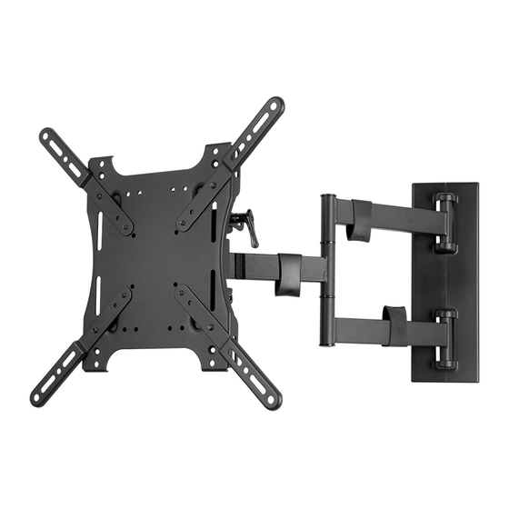
- Page 1 SM-CB-ART1-M Strong™ Carbon Series Universal Single Arm Articulating Mount for Medium Displays INSTALLATION MANUAL...
- Page 2 CAUTION The maximum weight of this wall mount is 100 lbs (45 kg). Use with heavier than the maximum weight indicated may result in instability causing possible injury. Le poids maximum de ce support mural est de 45 kg (100 lbs). L’utilisation avec ATTENTION un poids plus haut que le poids maximum indiqué...
-
Page 3: Installation
HARDWARE IMAGE DESCRIPTION ITEM QUANTITY BAG 1 Lag Bolt (A) 6.3 × 50 mm Lag Washer (B) 6.4 × 18 × 2 mm Concrete Anchor (C) 8 × 50 mm Screw (D) M4 × 20 mm Screw (E) M6 × 20 mm Screw (F) M6 ×... - Page 4 Wall Mounting of Arm Assembly If needed, hammer concrete anchors (C) into wall. ATTENTION: If anchors are going to be applied to a plastered concrete wall, the anchor must be recessed beyond the plaster to reside fully in the concrete. Apply lag washers (B) to lag bolts (A).
- Page 5 Mount Display Bracket to Display Panel Small Displays (Up to VESA 200x200) Attach display bracket to TV VESA holes using 4 bolts (D, E, F, G, H, or I) and washers (M or N); spacers (J, K, or L) may be required depending on display design. (see Figure 3). 200mm (7.8") 100mm (4") 75mm (3")
- Page 6 Lift the display and hook the two top bolts in grooves on top of the Mounting Head. Bottom studs will slide into roll adjustment slots. Once in position, reinstall wing nuts and secure the Adapter Plate to the Arm Assembly Head Mount. Arm Assembly Head Mount Display Panel...
-
Page 7: Tilt Adjustment
Installing Wall Plate Cover Included with the hardware pack are two halves of the wall plate cover assembly. Put the wall plate cover assembly together around the arms and slide onto wall plate. Wall Plate Cover Wall Plate Cover ADJUSTMENTS Tilt Adjustment Loosen Tilt Lever on the side of Mount Head (only enough to allow controlled adjustment) (Figure 8). -
Page 8: Contacting Technical Support
Phone: (866) 838-5052 Email: techsupport@snapav.com LIFETIME LIMITED WARRANTY Strong™ Mounts have a Lifetime Limited Warranty. This warranty includes parts and labor repairs on all components found to be defective in material or workmanship under normal conditions of Lifetime use. This warranty shall not apply to products which have been abused, modified or disassembled.