
Related Manuals for Bandai Namco DARK ESCAPE 4D


Summary of Contents for Bandai Namco DARK ESCAPE 4D
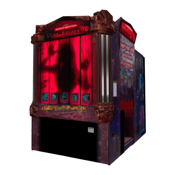
- Page 1 DARK ESCAPE 4D Operation Manual To ensure safe operation of the machine, be sure to read this Operation Manual before use. Keep this Operation Manual in a safe place for quick access whenever needed.
- Page 2 Introduction Thank you very much for purchasing DARK ESCAPE 4D (referred to as the “machine” in this manual). This Operation Manual describes: How to safely install, move, transport, operate, service and dispose of the machine. How to make full use of the machine’s functions and operate it correctly.
- Page 3 1. Safety Precautions -Be sure to read to ensure safe operation- Instructions to the Owner If you delegate the work for installing, moving, transporting, operating, servicing or disposing the machine to other people, ensure that these people read the relevant sections of this operation manual carefully before starting work, and observe the corresponding precautions.
- Page 4 1. Safety Precautions -Be sure to read to ensure safe operation- Critical Safety Precautions Should an abnormality occur, turn off the power switch immediately to stop operations. Then, be sure to disconnect the power cord plug from the outlet. Operating the machine while the abnormality persists may result in a or accident.
- Page 5 1. Safety Precautions -Be sure to read to ensure safe operation- Machine Warning Labels The warning labels contain important information for ensuring safety. Be sure to observe the following. • To ensure that the warning labels attached to the machine are always clearly visible, install the machine in an appropriate location with ample illumination and keep the labels clean at all times.
- Page 6 1. Safety Precautions -Be sure to read to ensure safe operation- Center assembly Warning sticker Service (B) EXP Part No.: 461-539 Front assembly Warning sticker Service (B) EXP Part No.: 461-539...
- Page 7 Table of Contents Introduction 1. Safety Precautions ............1 -Be sure to read to ensure safe operation- Levels of Risk ..........................1 Definition of “Technician” ......................... 1 Critical Safety Precautions ......................2 Machine Warning Labels ......................... 3 Table of Contents ........................5 2.
- Page 8 Table of Contents Test Mode ............................. 40 7-7-1 MENU Screen ...............................40 (a) Error Display when the Rack Assembly Internal Battery has Run Out ..............40 7-7-2 Game Cost and Related Settings (COIN OPTIONS) ....................42 7-7-3 Game Contents Settings (GAME OPTIONS) ......................43 7-7-4 Testing the Switches, Sensors and Other Components (I/O TEST) ..............45 (a) SWITCH TEST ...............................46...
- Page 9 Table of Contents 8. Technician’s Manual .............. 66 - Must be performed by a technician - 8A. Installation and Assembly ....................66 8A-1 Required Tools ..........................66 8A-2 Number of Workers and Work Time ....................66 8A-2-1 Number of Workers ...............................66 8A-2-2 Work Time ................................66 8A-3 Securing Work Space ........................
- Page 10 Table of Contents 8B-4 Removing, Installing and Replacing Assemblies and Parts ............104 8B-4-1 Front Assembly ..............................104 (1) Replacing the Rack Assembly ..........................104 (2) Replacing the Switching Regulator ........................106 (3) Replacing the MCD AMP PC Board ........................108 (4) Replacing the STRAIGHT PC Board ........................109 (5) Replacing the AIR CAN PC Board ........................
- Page 11 Table of Contents 10. Parts List ........................168 10-1 Front Assembly ........................... 168 10-2 Cord Box Assembly ........................170 10-3 Regulator Assembly ........................171 10-4 Transformer Assembly ........................ 172 10-5 Center Assembly ......................... 174 10-6 Service Plate Assembly ......................176 10-7 Gun Assembly 1/2 ........................
- Page 12 (1) Rated power supply One of the following power voltage is set at the factory: AC 110 V±10% (50/60 Hz) AC 120 V±10% (50/60 Hz) AC 220 V±10% (50/60 Hz) AC 230 V±10% (50/60 Hz) AC 240 V±10% (50/60 Hz) (2) Rated power consumption 380 W (3) Maximum current consumption...
- Page 13 2. Specifications 2) When disassembled Front assembly Width (W) 1410 x Depth (D) 830 x Height (H) 1930 [mm] Center assembly Width (W) 1410 × Depth (D) 830 × Height (H) 1120 [mm]...
- Page 14 2. Specifications Rear assembly Width (W) 1450 × Depth (D) 810 × Height (H) 1930 [mm] Rear top bar Width (W) 1440 × Depth (D) 110 × Height (H) 170 [mm] Wall assembly Roof reinforcement assembly Width (W) 1440 x Depth (D) 150 x Height (H) 170 [mm]...
- Page 15 2. Specifications Roof Width (W) 650 x Depth (D) 1430 x Height (H) 12 [mm] Side walls L and R Width (W) 1040 x Depth (D) 1840 x Height (H) 50 [mm] Signboard box assembly Width (W) 1010 × Depth (D) 150 × Height (H) 250 [mm] (9) Weight 1) When installed 525 kg...
- Page 16 3. Package Contents The following items are included when this machine is shipped. Make sure that all the items below are contained in the product package. If any items are missing, contact your distributor. Package 1/8 [FRONT ASSY] Weight: 167 kg W 1420 x D 840 x H 1930 [mm] Package 2/8 [CENTER ASSY] Weight: 88 kg...
- Page 17 3. Package Contents Package 3/8 [REAR ASSY] Weight: 190 kg W 1460 x D 830 x H 1930 [mm]...
- Page 18 Package 4/8 [ACCESSORIES A] Weight: 16 kg W 1120 x D 645 x H 340 [mm] Contents List Name Specification Qty. DARK ESCAPE 4D Operation Manual (this manual) USB dongle Anti-vibration pad Torx wrench Allen wrench 0.05 inches across flats 3D glasses...
- Page 19 3. Package Contents Name Specification Qty. Torx bolt (tamper proof) M5 x 16 (black) Phillips hexagon socket head bolt (with M6 x 40 spring washer) Square washer (large) Button head bolt M8 x 50 Flat washer (large) ø9 x 30 x t2.3 Corner cover (L) Corner cover (R) Top cover center...
- Page 20 3. Package Contents Package 5/8 [ACCESSORIES B] Weight: 24 kg W 1450 x D 370 x H 250 [mm] Contents List Name Specification Qty. FC middle bracket Coupling fixture Rear corner cover bracket Top cover support (R) Top cover support (L) Top harness cover Rear top bar Floor mat clamp (B) Signboard side bracket (R)
- Page 21 3. Package Contents Package 6/8 [SIGN BOX ASSY] Weight: 20 kg W 1070 x D 630 x H 230 [mm] Contents List Name Specification Qty. Signboard box Package 7/8 [SIDE WALL] Weight: 50 kg W 1900 x D 1100 x H 100 [mm] Contents List Name Specification Qty.
- Page 22 3. Package Contents Package 7/8 [ROOF] Weight: 12 kg W 1450 x D 665 x H 30 [mm] Contents List Name Specification Qty. Roof...
- Page 23 3. Package Contents MEMO...
- Page 24 4. Overall Structure (Part Names) * In this machine, the right side when viewing the LCD monitor from the front is designated as (R), and the left side as (L). Top cover side (L) [Front] Top cover center LED module Signboard box Top cover side (R) Side curtain Side wall L (The opposite side...
- Page 25 4. Overall Structure (Part Names) [Front and center assembly interior] LED module Ceiling tarpaulin Roof Air cannon outlet LCD monitor START button START button Gun assembly Gun assembly 2D/3D Switching button Rack assembly Front assembly Service panel R Regulator assembly Service panel L [Rear assembly interior] Eyeglasses strap Curly wire cord 3D glasses Rear assembly Glasses...
- Page 26 5. Delivery and Installation Conditions Install the machine according to the instructions in this Operation Manual and the procedures described in “8A. Installation and Assembly”. Failure to follow these instructions may result in a fire, electric shock, injury or malfunction. Fully insert the power cord plug into the outlet. Poor contact may generate heat and result in a fire or burns.
- Page 27 5. Installation 5-1-2 Play Zone for the Installed Machine Create a play zone around the machine so that players leaving the machine do not make contact with bystanders or passersby. W hen installing the machine, create a play zone as shown in the figure below. Be sure to secure this play zone, as it is also needed for service work. 2 m 75 cm or more 60 cm or more 60 cm or more...
- Page 28 5. Installation Required Dimensions for the Delivery Route (Such as Doors and Corridors) The delivery route sufficiently larger than the machine height and width must be secured. The sizes of the main parts of the machine when shipped are as follows. ...
- Page 29 5. Installation Rear assembly Width (W) 1450 × Depth (D) 810 × Height (H) 1930 [mm] Weight 190 kg Refer to the above dimensions and check beforehand that the machine can be carried in without problem. * When delivery is complete, go to “8A-4 Assembly” on page 68.
- Page 30 6. Moving and Transporting Do not leave the machine on a slope. It may fall over or result in an accident. When moving the machine, first attach the transport casters to the rear assembly, and then separate the assemblies and parts. Failure to do so may cause the machine to fall over or result in an accident.
- Page 31 6. Moving and Transporting Transporting 6-2-1 Transporting Manually (Such as Carrying on Stairs) Before transporting the machine manually, be sure to first attach the transport casters to the rear assembly, and then separate the front assembly, center assembly, rear assembly, signboard box assembly, curtain, side walls L and R, and roof. (See “8A-4 Assembly” on page 68.) When transporting the machine manually, be sure to use the following number of people. Overburdening yourself may result in an accident or injury.
- Page 32 6. Moving and Transporting 6-2-2 Loading and Unloading to and from a Vehicle Before transporting the machine manually, be sure to first attach the transport casters to the rear assembly, and then separate the front assembly, center assembly, rear assembly, signboard box assembly, curtain, side walls L and R, and roof. (See “8A-4 Assembly” on page 68.) When using a forklift to transport the front assembly, center assembly and rear assembly, observe the following.
- Page 33 6. Moving and Transporting 6-2-3 Transporting on a Vehicle When transporting the machine on a vehicle, secure the machine firmly so that it does not move during vehicle transport. Failure to secure the machine may result in an accident. When transporting the machine on a vehicle, attach the transport casters to the rear assembly. Failure to do so may cause the machine to fall over or result in an accident.
- Page 34 7. Operation Should an abnormality occur, turn off the power switch immediately to stop operations. Then, be sure to disconnect the power cord plug from the outlet. Operating the machine while the abnormality persists may result in a fire or accident. Dust accumulating on the power cord plug may result in a fire. Inspect the plug regularly and remove any dust. Fully insert the power cord plug into the outlet. Poor contact may generate heat and result in a fire or burns.
- Page 35 7. Operation Safety Precautions for Playing If players start feeling ill because of the game images or light stimulation, they must stop playing and take a break immediately. In rare cases, stimulation by lights or video images may cause the player to have a seizure or lose consciousness.
- Page 36 7. Operation Pre-operation Inspection Check the items below before starting machine operations. If there is an abnormality, resolve it by referring to “8B-2 Troubleshooting” on page 98. 7-4-1 Safety Inspection (Before Power On) Before operating the machine, check the following locations. This is required to prevent accidents or injuries.
- Page 37 7. Operation Inspect the following items after turning on the power switch. If you discover an abnormality, turn off the power switch immediately to stop operations. Then, disconnect the power cord plug from the outlet and contact your distributor. (14) Is any part of the power cord or plug abnormally hot? (15) Does touching the machine give a tingling electric shock? (16) Is there a burning smell, abnormal noise or vibration? (17) Is there any other abnormality or malfunction?
- Page 38 7. Operation Playing the Game If players start feeling ill because of the game images or light stimulation, they must stop playing and take a break immediately. In rare cases, stimulation by lights or video images may cause the player to have a seizure or lose consciousness.
- Page 39 7. Operation (3) Explanation of the Game System 1. Combination shots When playing in two-player mode, by bringing each gun’s crosshairs close to each other, the crosshairs become larger and players can use combination shots with high offensive power. Combination markers can be destroyed only by combination shots, and effective use of combination shots lets players destroy monsters more easily.
- Page 40 7. Operation Power Switch and Adjustment Switches 7-6-1 Power Switch Position and Turning the Power Switch On Turn on the power switch located inside the cord box on the rear of the front assembly. LAN cover Power switch Power cord Cord box assembly Do not turn the power switch on and off needlessly.
- Page 41 7. Operation 7-6-2 Adjustment Switches Use the supplied service key to open the service door of the center assembly for access to the adjustment switches. Service button cover Service door (a) Service button (red) Press this button to increase the credit count without operating the coin counter. (b) Test switch Set this switch to ON to enter Test mode.
- Page 42 7. Operation Test Mode 7-7-1 MENU Screen Open the service door of the center assembly and set the Test switch to ON. The MENU screen appears on the monitor. (See “7-6-1 Power Switch Position and Turning the Power Switch On” on page 38.) MENU Game cost and other settings See 7-7-2.
- Page 43 7. Operation Flip the Select switch up or down to select an item. The selected item blinks. Press the Enter button to enter the selection. After finishing the adjustments, select EXIT and press the Enter button. The monitor returns to the MENU screen. After finishing all the adjustments, set the Test switch to OFF.
- Page 44 7. Operation 7-7-2 Game Cost and Related Settings (COIN OPTIONS) This screen is used to make the game cost and free play settings. In the MENU screen on page 40, select COIN OPTIONS and press the Enter button. The COIN OPTIONS screen appears. COIN OPTIONS [DEFAULT IN GREEN] 2 CREDIT ( S ) GAME COST 1 CREDIT ( S )
- Page 45 7. Operation 7-7-3 Game Contents Settings (GAME OPTIONS) This screen is used to make various game settings. In the MENU screen on page 40, select GAME OPTIONS and press the Enter button. The GAME OPTIONS screen appears. Default settings are indicated in green. The only exception to this is HIT-COLOR, which is indicated in green when set to GREEN, or red when set to RED.
- Page 46 7. Operation Flip the Select switch up or down to select an item. The selected item blinks. Press the Enter button to enter the selection. After entering the selection, flip the Select switch up or down to change the item setting. After changing the setting, press the Enter button to return to the item selection.
- Page 47 7. Operation 7-7-4 Testing the Switches, Sensors and Other Components (I/O TEST) This screen is used to perform input/output tests for the various switches and other components. In the MENU screen on page 40, select I/O TEST and press the Enter button. The I/O TEST screen appears.
- Page 48 7. Operation (a) SWITCH TEST This screen is used to test the various switches and buttons. SWITCH TEST [ON:RED] COIN SERVICE TEST UP SELECT DOWN SELECT ENTER 1P GUN TRIGGER LEFT 1P GUN TRIGGER RIGHT OFF 1P START (10) 2P GUN TRIGGER LEFT (11) 2P GUN TRIGGER RIGHT OFF (12)
- Page 49 7. Operation (b) OUTPUT TEST (Cabinet Gimmick Test) This screen is used to switch each output (cabinet gimmick) on and off. OUTPUT TEST [ON:RED] 1P AIR CANON 2P AIR CANON 1P FAN LOW 1P FAN HIGH 2P FAN LOW 2P FAN HIGH VIBRATION SEAT LOW VIBRATION SEAT MID VIBRATION SEAT HIGH...
- Page 50 7. Operation (c) GUN TEST (Crosshairs and Gun Vibration Unit Check Screen) This screen is used to check the gun controller crosshairs and to check the gun vibration unit operation. In the I/O TEST screen on page 45, select GUN TEST and press the Enter button. The GUN TEST screen appears.
- Page 51 7. Operation GUN INITIALIZE (Crosshairs Adjustment Screen) This screen is used to separately adjust the 1P and 2P gun controller crosshairs. Be sure to perform this procedure during initial start-up. At the GUN TEST screen on page 48, press the Service switch to display the GUN INITIALIZE screen. * When switched to this screen, the gun crosshairs disappear.
- Page 52 7. Operation Follow the crosshair adjustment instructions displayed on the monitor, point the gun controller to be adjusted as far to the left as possible, and pull the trigger. Repeat the same operation in the right, up and down directions. Adjustment complete! Point at and shoot the...
- Page 53 7. Operation (d) VITAL SENSOR TEST (Startle Sensor Test) In the I/O TEST screen on page 45, select VITAL SENSOR TEST and press the Enter button. The VITAL SENSOR TEST screen appears. VITAL SENSOR TEST GRIP GUN TO SENSOR TEST 1P GRIP 1P VITAL SENSOR 2P GRIP 2P VITAL SENSOR ENTER SW:EXIT...
- Page 54 7. Operation (e) LED TEST This screen is used to test the LED lighting. In the I/O TEST Screen on page 45, select LED TEST and press the Enter button. The LED TEST screen appears. LED TEST [ON:RED] 1P START 2P START 2D/3D SWITCH CEILING LIGHT...
- Page 55 7. Operation 7-7-5 Monitor Adjustment (MONITOR TEST) This screen is used to make various monitor adjustments. In the MENU screen on page 40, select MONITOR TEST and press the Enter button. The MONITOR TEST screen appears. MONITOR TEST GRADATION PATTERN CROSSHATCH PATTERN FULL WHITE SCROLL PATTERN 3D VIEW PATTERN EXIT...
- Page 56 7. Operation (1) Gradation pattern (2) Crosshatch pattern (3) All-white pattern (4) Scrolling pattern (5) Stereoscopic pattern Select EXIT and press the Enter button to return to the MENU screen.
- Page 57 7. Operation 7-7-6 Sound Adjustment (SOUND TEST) This screen is used to perform volume adjustment, stereo checks and other settings. In the MENU screen on page 40, select SOUND TEST and press the Enter button. The SOUND TEST screen appears. SOUND TEST [DEFAULT IN GREEN] VOLUME GAME (0-15) 10...
- Page 58 7. Operation 7-7-7 Displaying and Initializing Game Data (BOOKKEEPING) This screen displays various game related data. In the MENU screen on page 40, select BOOKKEEPING and press the Enter button. The BOOKKEEPING screen appears on the monitor. This screen is used to view various game related data and initialize the data. Select EXIT and press the Enter button to return to the MENU screen.
- Page 59 7. Operation 7-7-8 Other Options (OTHERS) This screen is used to initialize the backup memory and perform other operations. When the backup memory is initialized, each item returns to the default setting. After initializing the backup memory, set each item again as necessary. In the MENU screen on page 40, select BOOKKEEPING and press the Enter button.
- Page 60 7. Operation Flip the Select switch up or down to select an item. The selected item blinks. Select EXIT and press the Enter button to return to the MENU screen. (a) Stereoscopic Display Setting (3D VIEW SETTING) This screen is used to set stereoscopic display. In the OTHERS screen on page 57, select 3D VIEW SETTING and press the Enter button.
- Page 61 7. Operation (b) Internal Clock Setting (CLOCK SETTING) This screen is used to set the internal clock. In the OTHERS screen on page 57, select CLOCK SETTING and press the Enter button. The CLOCK SETTING screen appears. CLOCK SETTING CLOCK 01/Aug/2012 WED 12:34:56 YEAR 01 + 2011 MONTH 08 Aug...
- Page 62 7. Operation (c) HDD CHECK This screen displays the HDD check contents. In the OTHERS Screen on page 57, select HDD CHECK and press the Enter button. The HDD CHECK screen appears. HDD CHECK MEDIA SYSTEM357HD ENTER SW:EXIT HDD CHECK screen Item Description (1) MEDIA...
- Page 63 7. Operation (d) Initializing the Backup Memory (BACKUP MEMORY INITIALIZE) This screen is used to initialize the backup memory. In the OTHERS screen on page 57, select BACKUP MEMORY INITIALIZE and press the Enter button. The message “BACKUP MEMORY INITIALIZE?” is displayed together with a NO/YES selection. Select YES to initialize the backup memory.
- Page 64 7. Operation 7-7-9 Software Update (SOFTWARE UPDATE) This screen is used to update the software. (This is normally not used.) In the MENU screen on page 40, select SOFTWARE UPDATE and press the Enter button. The SOFTWARE UPDATE screen appears. SOFTWARE UPDATE UPDATE EXIT...
- Page 65 7. Operation Error Display (For Operators) 7-8-1 Game Play Using Service Credits When playing a game paid for using credits that include credits added using the Service button, an asterisk (*) mark is displayed to the right of the credits display. * This asterisk mark is displayed when even one service credit is included.
- Page 66 7. Operation Gun Assembly Adjustment (Initialization) after Parts Replacement Be sure to initialize the gun assembly after replacing the rack assembly, USIO (T) PC board or gun assembly, or initializing the backup data. If the gun assembly is not initialized, the game cannot be played properly.
- Page 67 7. Operation 7-10 Cleaning Do not use alcohol, acetone or other organic solvents. This may degrade the materials. Do not use alkali or acidic cleansers. 7-10-1 Cleaning the 3D Glasses Wipe clean the lenses, temples and other parts that may touch the player’s face with the supplied glasses cleaning cloth (dry).
- Page 68 8. Technician’s Manual - Must be performed by a technician - 8A. Installation and Assembly Work is performed in dark locations such as inside the machine, so prepare adequate lighting before starting the work. 8A-1 Required Tools Prepare the following tools for the installation and assembly work. • Phillips screwdrivers (No.
- Page 69 8A. Installation and Assembly - Must be performed by a technician - 8A-3 Securing Work Space Secure a space of 60 cm to 1 m or more around the machine for performing the installation and assembly work. 2 m 75 cm or more 60 cm or more 60 cm or more Work space...
- Page 70 8A. Installation and Assembly - Must be performed by a technician - 8A-4 Assembly 8A-4-1 Connecting the Front Assembly and Center Assembly Remove the two Torx bolts (M5 x 30), and pull the service panel L at the lower left of the center assembly forward and down to remove it.
- Page 71 8A. Installation and Assembly - Must be performed by a technician - While being careful not to pinch the harnesses and connectors, join the front assembly and center assembly, and secure the assemblies to each other with two square washers (large) and two Phillips hexagon socket head bolts (with flat and spring washers) (M6 x 40) on each side (total four washers and four bolts).
- Page 72 8A. Installation and Assembly - Must be performed by a technician - Secure the FC middle bracket over the joint between the front assembly and center assembly with eight Torx bolts (M5 x 16). Torx bolt (M5 x 16) FC middle bracket * There is further assembly work to be performed, so leave the service panel L and service panel R open.
- Page 73 8A. Installation and Assembly - Must be performed by a technician - 8A-4-2 Attaching the 3D Glasses and Glasses Cleaning Cloths 3D glasses and glasses cleaning cloths are attached to both the L and R sides of the rear assembly. The description below explains how to attach the L side 3D glasses and glasses cleaning cloth.
- Page 74 8A. Installation and Assembly - Must be performed by a technician - Attaching the 3D Glasses Loosen one and remove the other button head bolt (M4 x 12) (silver) of the eye strap located above the 3D glasses case inside the rear assembly, thread the ring at the end of the curly wire cord onto the eye strap, and then reattach the removed bolt and tighten both bolts.
- Page 75 8A. Installation and Assembly - Must be performed by a technician - Attaching the Glasses Cleaning Cloths Fold over the corner of the glasses cleaning cloth with the fixing holes so that the fixing holes are aligned. Attach the glasses cleaning cloth securely to the inside of the rear assembly with the supplied Torx bolt (M5 x 8) (silver) and flat washer (ø5.5 x 20 x t1.0) (silver).
- Page 76 8A. Installation and Assembly - Must be performed by a technician - 8A-4-3 Installing the Wall Assemblies The description below explains how to install the L side. Perform the same procedure to install the R side. The wall assembly is installed while standing in a high location. Use a stool or ladder. Working in an unnatural body posture may result in injury or machine damage.
- Page 77 8A. Installation and Assembly - Must be performed by a technician - Secure the side wall L to the front assembly and center assembly with six flat washers (ø6.5 x 22 x t1.6) and six button head bolts (M6 x 30). Perform the same procedure to install the side wall R to the R side.
- Page 78 8A. Installation and Assembly - Must be performed by a technician - Connect the connector on top of the L side of the center assembly. Temporarily tighten the two Torx bolts (M5 x 16), insert and secure the supplied pillar bracket with one Torx bolt (M5 x 8), and then fully tighten the two Torx bolts.
- Page 79 8A. Installation and Assembly - Must be performed by a technician - Place the roof on top of the side wall L and side wall R from the front assembly side, and secure it with eight Torx bolts (M5 x 8) and two Torx bolts (M5 x 30). Torx bolt (M5 x 30) Roof reinforcement Roof...
- Page 80 8A. Installation and Assembly - Must be performed by a technician - 8A-4-4 Connecting the Center Assembly and Rear Assembly Insert the two coupling fixtures into the center assembly, and secure them with two flat washers (ø8.5 x 30 x t2.0) and two button head bolts (M8 x 50) each (total four washers and four bolts). Button head bolt (M8 x 50) Flat washer (ø8.5 x 30 x t2.0) Coupling fixture...
- Page 81 8A. Installation and Assembly - Must be performed by a technician - Secure the floor mat clamp (B) with four Torx bolts (M5 x 16) (silver). Rear assembly Floor mat clamp (B) Torx bolt (M5 x 16) (silver) Center assembly Remove the four flat washers (ø6.5 x 22 x t1.6) and four button head bolts (M6 x 30) from each side (total eight washers and eight bolts), and remove the two rear caster brackets from the back of the rear assembly.
- Page 82 8A. Installation and Assembly - Must be performed by a technician - 8A-4-5 Installing the Signboard Box Assembly The signboard box assembly is installed while standing in a high location. Use a stool or ladder. Working in an unnatural body posture may result in injury or machine damage. Insert the rear top bar horizontally onto the top of the rear assembly, and secure it with eight Torx bolts (M5 x 16).
- Page 83 8A. Installation and Assembly - Must be performed by a technician - Place the top harness cover over the harness, and secure it with two Torx bolts (M5 x 16). Torx bolt (M5 x 16) Top harness cover Loosen the eight Torx bolts (M5 x 16), and remove the two curtain supports from the bottom of the signboard box assembly.
- Page 84 8A. Installation and Assembly - Must be performed by a technician - Insert the tabs of the signboard box assembly into the insertion slots on top of the roof reinforcement and the rear top bar. ( ) Connect the connector. ( ) Rotate the signboard box assembly toward you so that it is right side up ( ), slide it toward the back to align the position ( ), and secure it with two flat washers (ø5.5 x 20 x t1.0) and four Torx bolts (M5 x 16).
- Page 85 8A. Installation and Assembly - Must be performed by a technician - 8A-4-6 Installing the Corner Covers (L) and (R) The description below explains how to install the L side. Perform the same procedure to install the R side. Install the corner cover bracket to the back corner of the rear assembly with two Torx bolts (M5 x 8). At this time, press the corner cover bracket upward when installing it.
- Page 86 8A. Installation and Assembly - Must be performed by a technician - 8A-4-7 Installing the Top Cover Center and Top Cover Sides (L) and (R) The top cover center, top cover side (L) and top cover side (R) are installed while standing in a high location.
- Page 87 8A. Installation and Assembly - Must be performed by a technician - Install the top cover support (L) to the L side of the rear assembly top surface with two Torx bolts (M5 x 16). Perform the same procedure to install the top cover support (R) to the R side. Top cover support (L) Torx bolt (M5 x 16) [L side]...
- Page 88 8A. Installation and Assembly - Must be performed by a technician - Insert the top cover center as shown in the figure, and secure the lower part to the top cover supports (L) and (R) with two flat washers (ø5.5 x 20 x t1.0) and two Torx bolts (M5 x 16). Torx bolt (M5 x 16) Flat washer (ø5.5 x 20 x t1.0) Top cover center...
- Page 89 8A. Installation and Assembly - Must be performed by a technician - 8A-4-8 Installing the Ceiling Tarpaulin and Side Curtains The description below explains how to install the L side. Perform the same procedure to install the R side. The ceiling tarpaulin and side curtains are installed while standing in a high location. Use a stool or ladder.
- Page 90 8A. Installation and Assembly - Must be performed by a technician - Hook the ceiling tarpaulin over the four Torx bolts (M5 x 16) on the bottom of the signboard box assembly. (Four locations per side, total eight locations) Torx bolt (M5 x 16) Torx bolt (M5 x 16) Ceiling tarpaulin Signboard box...
- Page 91 8A. Installation and Assembly - Must be performed by a technician - Orient the side curtain so that the printing faces the outside, and hook it over the four outer Torx bolts (M5 x 16) on the bottom of the signboard box assembly. Torx bolt (M5 x 16) Torx bolt (M5 x 16) Side curtain...
- Page 92 8A. Installation and Assembly - Must be performed by a technician - 8A-4-9 Level Adjuster Adjustment After the machine is fully assembled, place anti-vibration pads below the total ten level adjusters of the front assembly, center assembly and rear assembly, and then lower the level adjusters according to “5-1 Installation Conditions”...
- Page 93 8A. Installation and Assembly - Must be performed by a technician - 8A-5 Inserting the USB Dongle Insert the USB dongle firmly into the USB1 slot of the rack assembly located inside the service door R on the R side of the center assembly. Rack assembly [USB 1] slot USB dongle...
- Page 94 8A. Installation and Assembly - Must be performed by a technician - 8A-6 Connecting the Communication Cables *Network compatible models only (1) Connection Method To avoid electric shock, accidents or injuries to yourself or other people, or damage to the electronic circuits, be sure to turn off the power switch before starting work. ...
- Page 95 8A. Installation and Assembly - Must be performed by a technician - 8A-7 Connecting the Power Cord and Ground Be sure to install the ground wire using the method below. Failure to install the ground wire may result in electric shock in the event of electrical leakage. (1) Connect the ground using a 3P plug.
- Page 96 8A. Installation and Assembly - Must be performed by a technician - 8A-7-2 Connecting the Power Cord to the Outlet (1) In case of a 3P outlet Insert the power cord plug into the outlet. The shape and specification of the power cord plug and outlet may vary depending on the country. Power cord plug 3-pin outlet...
- Page 97 8A. Installation and Assembly - Must be performed by a technician - 8A-8 Power Switch Position and Turning the Power Switch 8A-8-1 Turning the Power Switch On Turn on the power switch located inside the cord box assembly on the back of the front assembly. Power switch Cord box assembly ...
- Page 98 8A. Installation and Assembly - Must be performed by a technician - 8A-9 Checks after Installation Check the following items. Have all parts been installed and assembled according to the instructed procedures? Are any screws or bolts loose, fallen out or missing? • Have all screws and bolts in installation and assembly locations been tightened? • Are any screws or bolts in other than installation and assembly locations loose, fallen out or missing? • O ther inspections concerning safety and functionalities (See “7-4 Pre-operation Inspection”...
- Page 99 8B. Service To avoid electric shock, accidents or injuries to yourself or other people, be sure to turn off the power switch before performing service work (such as repairs or correcting malfunctions). 8B-1 Inspection and Service Perform periodic service. Failure to perform service may result in an accident. ...
- Page 100 8B. Service - Must be performed by a technician - 8B-2 Troubleshooting To avoid electric shock, accidents or injuries to yourself or other people, or damage to the electronic circuits, be sure to turn off the power switch before starting work If the problem is not described in “8B-2 Troubleshooting” or the problem persists despite taking the appropriate action, turn off the power switch immediately to stop operations, and contact your distributor.
- Page 101 8B. Service - Must be performed by a technician - 8B-2-2 Front Assembly Symptom Cause Action Reference page • Images are not displayed on • A monitor connector is • Check the connector Page 114 the monitor. disconnected. connections. • A rack assembly connector is • Check the connector Page 104 disconnected.
- Page 102 8B. Service - Must be performed by a technician - 8B-2-4 Gun Assembly Symptom Cause Action Reference page • The gun does not function. • The variable registor is not • Perform initialization in Test Page 49 initialized. mode. • A connector is disconnected. • Insert the connector securely.
- Page 103 8B. Service - Must be performed by a technician - 8B-2-5 Rear Assembly Symptom Cause Action Reference page • The seat does not vibrate. • A connector is disconnected. • Insert the connector securely. Page 141 • A MONITOR IF PC Board • Replace the MONITOR IF PC Page 142 malfunction.
- Page 104 8B. Service - Must be performed by a technician - 8B-3 Error Display (For Technicians) Symptom Cause Action Reference page 1-1 COIN ERROR • The coin selector is jammed. • Check the coin selector and – resolve the trouble. • A coin selector malfunction. • Replace the coin selector.
- Page 105 8B. Service - Must be performed by a technician - Symptom Cause Action Reference page 20-1 • The version update file is • Contact your distributor. – VERSION UP ERROR corrupted. 20-2 • Insert the version update USB • Contact your distributor. –...
- Page 106 8B. Service - Must be performed by a technician - 8B-4 Removing, Installing and Replacing Assemblies and Parts 8B-4-1 Front Assembly (1) Replacing the Rack Assembly To avoid electric shock, accidents or injuries to yourself or other people, or damage to the electronic circuits, be sure to turn off the power switch before starting work.
- Page 107 8B. Service - Must be performed by a technician - Remove the six countersunk nuts (M6), and remove and replace the rack assembly. Rack assembly Countersunk nut (M6) Countersunk nut (M6) Rack board To install, perform the procedure in reverse. ...
- Page 108 8B. Service - Must be performed by a technician - (2) Replacing the Switching Regulator To avoid electric shock, accidents or injuries to yourself or other people, or damage to the electronic circuits, be sure to turn off the power switch before starting work. ...
- Page 109 8B. Service - Must be performed by a technician - Select the switching regulator to be replaced, disconnect the two or three connectors from the regulator base, remove the four or five cap screws (M) (M3 x 6), and remove and replace the switching regulator. Cap screw (M) (M3 x 6) Connector...
- Page 110 8B. Service - Must be performed by a technician - (3) Replacing the MCD AMP PC Board To avoid electric shock, accidents or injuries to yourself or other people, or damage to the electronic circuits, be sure to turn off the power switch before starting work. ...
- Page 111 8B. Service - Must be performed by a technician - (4) Replacing the STRAIGHT PC Board To avoid electric shock, accidents or injuries to yourself or other people, or damage to the electronic circuits, be sure to turn off the power switch before starting work. ...
- Page 112 8B. Service - Must be performed by a technician - Remove the three Torx bolts (M5 x 16), and remove the cord box assembly from the back of the front assembly. Back of front assembly Torx bolt (M5 x 16) Cord box assembly Torx bolt (M5 x 16) Remove the four cap screws (M) (M3 x 6), and remove and replace the STRAIGHT PC board.
- Page 113 8B. Service - Must be performed by a technician - (5) Replacing the AIR CAN PC Board To avoid electric shock, accidents or injuries to yourself or other people, or damage to the electronic circuits, be sure to turn off the power switch before starting work. ...
- Page 114 8B. Service - Must be performed by a technician - Disconnect the three connectors and the Faston terminal, remove the two flange socket bolts (M4 x 15), and remove the AIR CAN PCB bracket. Flange socket bolt (M4 x 15) Connector Faston terminal Flange socket bolt (M4 x 15)
- Page 115 8B. Service - Must be performed by a technician - (6) Replacing the Air Cannon Speaker To avoid electric shock, accidents or injuries to yourself or other people, or damage to the electronic circuits, be sure to turn off the power switch before starting work. ...
- Page 116 8B. Service - Must be performed by a technician - (7) Replacing the LCD Monitor To avoid electric shock, accidents or injuries to yourself or other people, or damage to the electronic circuits, be sure to turn off the power switch before starting work. ...
- Page 117 8B. Service - Must be performed by a technician - Remove the four Phillips hexagon socket head bolts (with flat and spring washers) (M6 x 16), tilt the top of the LCD monitor toward you, and then lift up and remove the LCD monitor. Phillips hexagon socket head bolt (with flat and spring washers) (M6 x 16) LCD monitor Phillips hexagon socket head bolt (with flat and spring washers) (M6 x 16)
- Page 118 8B. Service - Must be performed by a technician - 8B-4-2 Center Assembly (1) Replacing the USIO (T) PC Board To avoid electric shock, accidents or injuries to yourself or other people, or damage to the electronic circuits, be sure to turn off the power switch before starting work. ...
- Page 119 8B. Service - Must be performed by a technician - Remove the five Phillips pan head screws (with flat and spring washers) (M3 x 10), and remove and replace the USIO (T) PC board. USIO (T) PC board Phillips pan head screw (with flat and spring washers) (M3 x 10) To install, perform the procedure in reverse.
- Page 120 8B. Service - Must be performed by a technician - (2) Replacing the GUN DRIVE PC Board To avoid electric shock, accidents or injuries to yourself or other people, or damage to the electronic circuits, be sure to turn off the power switch before starting work. ...
- Page 121 8B. Service - Must be performed by a technician - (3) Replacing the Illuminated Switch and LED Lamp of the 2D/3D Switching Button To avoid electric shock, accidents or injuries to yourself or other people, or damage to the electronic circuits, be sure to turn off the power switch before starting work.
- Page 122 8B. Service - Must be performed by a technician - Replace the illuminated switch or LED lamp, and then install by reversing the procedure. LED lamp “+” mark Illuminated switch “+” mark When installing the LED lamp, be careful to insert the LED lamp with the correct orientation. ...
- Page 123 8B. Service - Must be performed by a technician - 8B-4-3 Gun Assembly The description below explains how to remove and install the L side. Perform the same procedure to remove and install the R side. (1) Removing and Installing the Gun Assembly ...
- Page 124 8B. Service - Must be performed by a technician - (2) Replacing the Variable Registor (for Right/Left) To avoid electric shock, accidents or injuries to yourself or other people, or damage to the electronic circuits, be sure to turn off the power switch before starting work. Turn off the power switch of the machine.
- Page 125 8B. Service - Must be performed by a technician - Disconnect the connector, remove the two Phillips pan head screws (with flat and spring washers) (M4 x 12), and remove the variable registor bracket (1). Connector Phillips pan head screw (with flat and spring washers) (M4 x 12) Variable registor bracket (1) Loosen the set screw (M4 x 6), and remove the variable registor gear.
- Page 126 8B. Service - Must be performed by a technician - Remove the hexagon nut, spring washer and flat washer, and remove the variable registor (for right/ left) from the variable registor bracket (1). Replace the variable registor. Variable registor Protrusion (for Right/Left) Flat washer Spring washer...
- Page 127 8B. Service - Must be performed by a technician - (3) Replacing the Variable Registor (for Up/Down) To avoid electric shock, accidents or injuries to yourself or other people, or damage to the electronic circuits, be sure to turn off the power switch before starting work. Turn off the power switch of the machine.
- Page 128 8B. Service - Must be performed by a technician - Remove the variable registor (for up/down) from the variable registor bracket (2). Terminals Variable registor (for up/down) Protrusion Flat washer Variable registor Hole Spring washer Hexagon nut (Do not over-tighten) Variable registor bracket (2) Brown Red Black Replace the variable registor (for up/down).
- Page 129 8B. Service - Must be performed by a technician - (4) Replacing the Micro Switch To avoid electric shock, accidents or injuries to yourself or other people, or damage to the electronic circuits, be sure to turn off the power switch before starting work. Turn off the power switch of the machine.
- Page 130 8B. Service - Must be performed by a technician - W hen installing, check the connector orientation, and insert the connector firmly until it locks securely. When installing, be careful not to pinch the connectors and harness. To install, perform the procedure in reverse. A fter replacement, be sure to check operation in Test mode. (See “7-7-4(a) SWITCH TEST” on page 46.) (5) Replacing the Trigger and Spring ...
- Page 131 8B. Service - Must be performed by a technician - (6) Replacing the Illuminated Switch and LED Lamp of the START Button To avoid electric shock, accidents or injuries to yourself or other people, or damage to the electronic circuits, be sure to turn off the power switch before starting work. Turn off the power switch of the machine.
- Page 132 8B. Service - Must be performed by a technician - Remove the LED lamp from the illuminated switch, and replace the LED lamp. * The LED lamp has plus and minus marks. When replacing, be careful to align the LED lamp correctly. LED lamp “+”...
- Page 133 8B. Service - Must be performed by a technician - (7) Replacing the Vibration Unit To avoid electric shock, accidents or injuries to yourself or other people, or damage to the electronic circuits, be sure to turn off the power switch before starting work. Turn off the power switch of the machine.
- Page 134 8B. Service - Must be performed by a technician - Loosen the two set screws (M5 x 10), and remove the crank. Disconnect the connector. Remove the three Phillips pan head screws (with flat and spring washers) (M4 x 8), and remove and replace the vibration unit.
- Page 135 8B. Service - Must be performed by a technician - (8) Replacing the Gun Harness 2 To avoid electric shock, accidents or injuries to yourself or other people, or damage to the electronic circuits, be sure to turn off the power switch before starting work. Turn off the power switch of the machine.
- Page 136 8B. Service - Must be performed by a technician - Pull out the gun harness 2. Gun harness 2 To install, perform the procedure in reverse.
- Page 137 8B. Service - Must be performed by a technician - (9) Replacing the Gun Harness 5 To avoid electric shock, accidents or injuries to yourself or other people, or damage to the electronic circuits, be sure to turn off the power switch before starting work. Turn off the power switch of the machine.
- Page 138 8B. Service - Must be performed by a technician - (10) Replacing the VSS Module To avoid electric shock, accidents or injuries to yourself or other people, or damage to the electronic circuits, be sure to turn off the power switch before starting work. Turn off the power switch of the machine.
- Page 139 8B. Service - Must be performed by a technician - Disconnect the two connectors, remove the four Phillips pan head screws (with flat and spring washers) (M3 x 10), and remove and replace the SENSOR IF PC board. Connector Phillips pan head screw (with flat and spring washers) (M3 x 10) SENSOR IF PC board...
- Page 140 8B. Service - Must be performed by a technician - 8B-4-4 Rear Assembly (1) Replacing the Switching Regulator To avoid electric shock, accidents or injuries to yourself or other people, or damage to the electronic circuits, be sure to turn off the power switch before starting work. Turn off the power switch of the machine.
- Page 141 8B. Service - Must be performed by a technician - Disconnect the three connectors, remove the four Phillips pan head screws (with flat and spring washers) (M3 x 10), and remove and replace the switching regulator (12V). Switching regulator Phillips pan head screw (with flat and spring washers) (M3 x 10) Connector Switching regulator Phillips pan head screw...
- Page 142 8B. Service - Must be performed by a technician - (2) Replacing the LAM DRIVE PC Board To avoid electric shock, accidents or injuries to yourself or other people, or damage to the electronic circuits, be sure to turn off the power switch before starting work. Turn off the power switch of the machine.
- Page 143 8B. Service - Must be performed by a technician - (3) Replacing the Speed Control Driver To avoid electric shock, accidents or injuries to yourself or other people, or damage to the electronic circuits, be sure to turn off the power switch before starting work. Turn off the power switch of the machine.
- Page 144 8B. Service - Must be performed by a technician - (4) Replacing the MOTOR IF PC Board To avoid electric shock, accidents or injuries to yourself or other people, or damage to the electronic circuits, be sure to turn off the power switch before starting work. Turn off the power switch of the machine.
- Page 145 8B. Service - Must be performed by a technician - (5) Replacing the DC Brushless Motor and Rotor Cover To avoid electric shock, accidents or injuries to yourself or other people, or damage to the electronic circuits, be sure to turn off the power switch before starting work. Turn off the power switch of the machine.
- Page 146 8B. Service - Must be performed by a technician - Remove the seven Torx bolts (M5 x 8), and remove the support bracket from the seat assembly. Seat assembly Torx bolt (M5 x 8) Seat guard tarpaulin Support bracket Lift up the seat guard tarpaulin, and remove the four Phillips hexagon socket head bolts (with flat and spring washers) (M6 x 25) from inside the seat assembly.
- Page 147 8B. Service - Must be performed by a technician - Remove the seat assembly, and place it upside down onto a piece of carpet or cardboard laid out on the floor. Seat assembly Carpet or cardboard Remove the eight countersunk washer nuts (M5), and remove the seat motor bracket. Countersunk washer nut (M5) Seat motor bracket Countersunk washer nut...
- Page 148 8B. Service - Must be performed by a technician - Remove the four cap screws (M) (M5 x 8), and remove the seat motor cover. Cap screw (M) (M5 x 8) Cap screw (M) (M5 x 8) Seat motor cover Loosen the flange socket bolt (M6 x 8), and remove the weight and the weight spacer.
- Page 149 8B. Service - Must be performed by a technician - Disconnect the connector, open the cord clamp, remove the four cap bolts (M6 x 18) and four countersunk washer nuts (M6), and remove and replace the DC brushless motor. Rotor cover Cord clamp Connector Cap bolt...
- Page 150 8B. Service - Must be performed by a technician - (6) Replacing the Rear Seat Cushion To avoid electric shock, accidents or injuries to yourself or other people, or damage to the electronic circuits, be sure to turn off the power switch before starting work. Turn off the power switch of the machine.
- Page 151 8B. Service - Must be performed by a technician - Remove the 18 countersunk washer nuts (M5), and remove the seat support angles (A) and (B) and the seat motor bracket. Countersunk washer nut (M5) Seat support angle (B) Countersunk washer nut (M5) Seat motor bracket Countersunk washer nut (M5) Seat support angle...
- Page 152 8B. Service - Must be performed by a technician - (7) Replacing LED Modules Replacing a LED module inside the rear sign panel. To avoid electric shock, accidents or injuries to yourself or other people, or damage to the electronic circuits, be sure to turn off the power switch before starting work.
- Page 153 8B. Service - Must be performed by a technician - Hold the grips of the rear sign panel, lift up slightly, and then pull downward and out to remove the panel. Grip Grip Rear sign panel Remove the eight flat washers (ø5.5 x 20 x t1.0) and eight Phillips pan head screws (with flat and spring washers) (M5 x 12), and remove the rear sign sheet.
- Page 154 8B. Service - Must be performed by a technician - Remove the two Phillips pan head screws (with flat and spring washers) (M4 x 20) securing the LED tube caps U and L at the top and bottom of the LED tube containing the LED module to be replaced, disconnect the connector, and then remove the LED tube.
- Page 155 8B. Service - Must be performed by a technician - To install, perform the procedure in reverse. When installing, lock the connectors securely. When installing, be careful not to pinch the connectors and harness. After replacing the LED module, turn on the power switch and check the LED lighting operation.
- Page 156 8B. Service - Must be performed by a technician - Replacing the LED module at the front of the top cover center To avoid electric shock, accidents or injuries to yourself or other people, or damage to the electronic circuits, be sure to turn off the power switch before starting work.
- Page 157 8B. Service - Must be performed by a technician - Remove the LED tube caps U and L, and remove and replace the LED module. LED tube Cap U LED tube Cap U (back) * (with U-shaped notch) Protrusion LED tube Connector cord LED tube Connector...
- Page 158 8B. Service - Must be performed by a technician - (8) Replacing the 3D Glasses 3D glasses are attached to both the L and R sides of the rear assembly. The description below explains how to replace the 3D glasses on the L side. Perform the same procedure to replace the 3D glasses on the R side. ...
- Page 159 8B. Service - Must be performed by a technician - (9) Replacing the Glasses Cleaning Cloth Glasses cleaning cloths are attached to both the L and R sides of the rear assembly. The description below explains how to replace the glasses cleaning cloths on the L side. Perform the same procedure to replace the glasses cleaning cloths on the R side.
- Page 160 8B. Service - Must be performed by a technician - 8B-4-5 Signboard Box Assembly (1) Replacing LED Modules The description below explains how to remove and install the L side. Perform the same procedure to remove and install the R side. ...
- Page 161 8B. Service - Must be performed by a technician - Remove the two countersunk washer nuts (M4), disconnect the connector, and remove the LED tube. Countersunk washer nut (M4) LED tube Connector Remove the LED tube caps U and L, and remove and replace the LED module. LED tube Cap U LED tube Cap U (back) * (with U-shaped notch)
- Page 162 8B. Service - Must be performed by a technician - 8B-4-6 Wall Assembly (1) Replacing LED Modules To avoid electric shock, accidents or injuries to yourself or other people, or damage to the electronic circuits, be sure to turn off the power switch before starting work. Turn off the power switch of the machine.
- Page 163 8B. Service - Must be performed by a technician - Remove the LED tube caps U and L, and remove and replace the LED module. LED tube Cap U LED tube Cap U (back) * (with U-shaped notch) Protrusion LED tube Connector cord LED tube Connector...
- Page 164 8B. Service - Must be performed by a technician - 8B-5 LCD Monitor Adjustment To avoid electric shock, accidents or injuries to yourself or other people, or damage to the electronic circuits, be sure to turn off the power switch before starting work. ...
- Page 165 8B. Service - Must be performed by a technician - Open the cord clip, and pull the monitor adjustment switches around the outside of the front assembly to a position from where the monitor screen can be seen. Monitor adjustment switch LCD monitor Turn on the power switch and adjust the LCD monitor.
- Page 166 8B. Service - Must be performed by a technician - 8B-5-2 LCD Monitor Picture Quality Adjustment Move the monitor adjustment switches to a position from where the monitor images can be checked. (See “8B-5-1 Removing and Installing the Monitor Adjustment Switches” on page 162.) Turn on the power switch of the machine (cabinet), and also turn on the power switch of the LCD monitor if it is off.
- Page 167 8B. Service - Must be performed by a technician - 8B-5-3 LCD Monitor Settings Move the monitor adjustment switches to a position from where the monitor images can be checked. (See “8B-5-1 Removing and Installing the Monitor Adjustment Switches” on page 162.) Turn on the power switch of the machine (cabinet), and also turn on the power switch of the LCD monitor if it is off.
- Page 168 9. Disposal When disposing of the machine, follow the applicable regulations for collection, transportation and disposal. When delegating the collection, transportation and disposal of the machine, be sure to delegate to specialists in each field. Dispose of used lithium batteries in accordance with applicable regulations. ...
- Page 169 MEMO...
- Page 170 10. Parts List 10-1 Front Assembly Rack assembly Rack assembly Transformer assembly Regulator assembly 47-inch monitor Rack assembly Cord box assembly...
- Page 171 10. Parts List Name Qty. Type and rating Part No. Front cabinet XDE-730-980 Service panel U XDE-730-981 Service panel L XDE-730-982 Rack board XDE-730-983 Front plate XDE-730-984 Monitor panel retainer upper XDE-730-985 Monitor panel retainer lower XDE-730-986 Monitor panel retainer side XDE-730-987 Fan plate XDE-730-988...
- Page 172 10. Parts List 10-2 Cord Box Assembly Ground terminal Name Qty. Type and rating Part No. Cord box XDE-731-020 LAN cover XDE-731-021 10GEEG3E-R XDE-007-205 Circuit Protector ICP30-L-11-608-10-Z811 (AC 110V) 000-743 ICP30-L-11-608-5-Z811 (AC 230V) XDE-000-744 straight PCB 2642 9601 XDE-307-308...
- Page 173 10. Parts List 10-3 Regulator Assembly MCD AMP PCB assembly Name Qty. Type and rating Part No. Regulator base XDE-731-025 Switching regulator (5V) VS50E-5 XDE-009-250 Switching regulator (12 V) VS100E-12 XDE-009-270 Switching regulator (24V) VS150E-24 XDE-009-269 Switching regulator (36V) LEP150F-36 XDE-009-271...
- Page 174 10. Parts List 10-4 Transformer Assembly Name Qty. Type and rating Part No. Transformer base XDE-731-030 Insulated transformer S133V100PV XDE-004-746...
- Page 175 10. Parts List MEMO...
- Page 176 10. Parts List 10-5 Center Assembly V406 USIO (T) PCB assembly Gun assembly Service plate assembly Gun assembly...
- Page 177 10. Parts List Name Qty. Type and rating Part No. Center cabinet XDE-731-034 Floor mat XDE-731-035 Floor mat clamp XDE-731-036 Service panel L XDE-731-037 Service panel R XDE-731-038 Key washer XDE-450-124 USIO PCB base XDE-731-040 FC middle bracket XDE-731-041 Switch base XDE-731-042 Gun mount bracket L XDE-731-043...
- Page 178 10. Parts List 10-6 Service Plate Assembly Name Qty. Type and rating Part No. Service plate XDE-731-065 Service switch cover XDE-731-066 Service sticker M (B) XDE-461-722 Slide switch SDS-103A-03#13BJ XDE-000-681 Push button SDP-103C-22RB XDE-000-336 Push button SDP-103C-22GB XDE-000-619 Toggle switch SDSA-331G-CR XDE-000-337...
- Page 179 10. Parts List MEMO...
- Page 180 10. Parts List 10-7 Gun Assembly 1/2 Vibration unit [See detailed view.] Vibration unit Notch position D-cut, black dot direction Notch position Top side Back side Assembly detailed view Assembly detailed view...
- Page 181 10. Parts List Name Qty. Type and rating Part No. Neck XDE-731-070 Core shaft XDE-724-771 Gun base box XDE-731-071 Frame cover (2) XDE-731-072 Frame cover (1) XDE-731-073 Switch base XDE-731-074 Grip XDE-731-075 Stopper shaft XDE-724-076 Stopper rubber (1) XDE-724-776 Motor frame XDE-724-778 Stopper frame XDE-724-779...
- Page 182 10. Parts List 10-7 Gun Assembly 2/2 Vibration unit [See detailed view.] Vibration unit Notch position D-cut, black dot direction Notch position Top side Back side Assembly detailed view Assembly detailed view...
- Page 183 10. Parts List Name Qty. Type and rating Part No. Slide rail AR2-60 (2 x 10 balls) XDE-107-166 Rotary solenoid RSR20/10-CAB0-BNG XDE-004-666 Micro switch D3M-01L1-3 XDE-000-673 Illuminated switch 75-L012-61 XDE-000-846 Variable resistor RVQ24YN04-06 20F B102 (60°) XDE-008-079 Variable resistor RVQ24YN0406 20F B102 XDE-008-077 VSS module Vital signs sensor and sensor IF PC board...
- Page 184 10. Parts List 10-8 Rear Assembly 1/4 (Insert into Used to secure...
- Page 185 10. Parts List Name Qty. Type and rating Part No. Top cover side support XDE-731-113 3D glasses case XDE-731-132 Corner cover (L) XDE-731-133 Corner cover (R) Mirror image of 3 XDE-731-134 Top cover center XDE-731-135 Top cover side (L) XDE-731-136 Top cover side (R) XDE-731-137 Well nut...
- Page 186 10. Parts List 10-8 Rear Assembly 2/4 Speed control driver LAM DRIVE PC board MOTOR IF PC board (Opposite side...
- Page 187 10. Parts List Name Qty. Type and rating Part No. Rear cabinet XDE-731-095 Rear cabinet back door XDE-731-096 Rear back cushion XDE-731-097 Rear seat cushion XDE-731-098 Rear corner base (R) XDE-731-099 Rear corner base (L) XDE-731-100 Rear corner pipe XDE-731-101 Rear corner cover bracket XDE-731-102 Rear sign panel angle (S)
- Page 188 10. Parts List 10-8 Rear Assembly 3/4 Speed control driver LAM DRIVE PC board MOTOR IF PC board (Opposite side...
- Page 189 10. Parts List Name Qty. Type and rating Part No. Locking wire XDE-731-152 Embedded pulls (for t15) XDE-101-247 Rope hook (F) XDE-450-417 Seat hook XDE-724-755 LED tube Cap L XDE-727-162 LED tube Cap U XDE-727-161 LED tube XDE-727-163 Anti-vibration rubber (ring mount) XDE-731-153 Eye strap (SUS) TIS-5...
- Page 190 10. Parts List 10-8 Rear Assembly 4/4 (Opposite side Rear assembly 1/4 Rear assembly 1/4 (Pages 182, 183) (Pages 182, 183) Rear assembly 2/4 (Pages 184, 185) Rear assembly 2/4 Rear assembly 2/4 (Pages 184, 185) (Pages 184, 185) Rear assembly 2/4 (Pages 184, 185) Rear assembly 1/4 (Pages 182, 183)
- Page 191 10. Parts List Name Qty. Type and rating Part No. Corner base sticker (L) XDE-731-138 Corner base sticker (R) Mirror image of 1 XDE-731-139 Rear angle sticker (EXP) XDE-731-226 Rear cabinet sticker (L) XDE-731-141 Rear cabinet sticker (R) XDE-731-142 Top cover sticker (EXP) XDE-731-227 3D glasses case sticker (EXP) XDE-731-228...
- Page 192 10. Parts List 10-9 Signboard Box Assembly (Opposite side Name Qty. Type and rating Part No. Signboard box XDE-731-170 Curtain support XDE-731-171 Side sign panel EXP XDE-731-223 LED tube Cap L XDE-727-162 LED tube Cap U XDE-727-161 LED tube XDE-727-163 LED module LM-B-RDX24-50006-W100-C XDE-002-651...
- Page 193 10. Parts List 10-10 Wall Assembly (Opposite side Name Qty. Type and rating Part No. Side wall XDE-731-190 Roof XDE-731-191 Side reinforcement R XDE-731-192 Side reinforcement L XDE-731-193 Roof reinforcement XDE-731-194 LED panel XDE-731-195 Side pillar R XDE-731-196 Side pillar L XDE-731-197 Pillar bracket XDE-731-198...
- Page 194 10. Parts List 10-11 Other Parts...
- Page 195 10. Parts List Name Qty. Type and rating Part No. DARK ESCAPE Operation Manual (EXP) (this manual) XDE-731-220 3D glasses XDE-730-961 Glasses cleaning cloth XDE-730-962 Anti-vibration pad KHL-10-100-0001 XDE-106-204 Side curtain EXP XDE-731-224 Ceiling tarpaulin XDE-731-181 LAN cable 20 m LAN20.0m GB-BNG XDE-007-928...
- Page 196 10. Parts List...
- Page 197 11. Wiring Diagram 11-1 Overall Wiring Diagram =ALL.AA10 Front Assy (EXP) =ALL.AA10.AA12 Regulator Assy -X109 -X380 -X438 VL 12P-R VL 12P-P YL 21P-P YL 21P-R .2/7.A7 SPOUT FL+ .2/7.D4 SPOUT FL+ SPOUT FL- SPOUT FL- .2/7.D4 .2/7.A7 SPOUT FR+ SPOUT FR+ .2/7.D4 LT.BU LT.BU...
- Page 198 11. Wiring Diagram 11-2 Overall Wiring Diagram =ALL.AA10 =ALL.AA20 Front Assy (EXP) Center Assy -X403 -X433 VL 3P-P VL 3P-R AWG 16 AWG 16 #1430 .1/7.A4 .7/7.E1 AWG 16 AWG 16 #1430 .1/7.A4 .7/7.E1 GN/YE GN/YE #1430 .1/7.A4 .7/7.E1 -CB53.X1 USB A Female Heder USB A(P) -CB53...
- Page 199 11. Wiring Diagram 11-3 Overall Wiring Diagram =ALL.AA20 Center Assy =ALL.AA20.AA22 -H138 -H145 Gun Assy (LEFT) 12VDC 12VDC .1/7.F10 .4/7.A3 12VDC .4/7.B6 -H185 -H147 EARTH EARTH .1/7.G10 .4/7.A3 -X415 -FG28 VH 2P-P VH 2P-H .1/7.F10 HGND -X411 XAD 12P-P XAD 12P-H -X416 -X210 -X235...
- Page 200 11. Wiring Diagram 11-4 Overall Wiring Diagram =ALL.AA20 =ALL.AA50 Center Assy Wall Assy -X302 -X303 -X304 -X301 -X305 YL 3P-P YL 3P-R XA 2P-P XA 2P-R SM 2P-P SM 2P-R Supplied 12VDC wire .3/7.A8 12VDC -LED25 EARTH GN/YE GN/YE .3/7.A8 Supplied wire LED Module...
- Page 201 11. Wiring Diagram 11-5 Overall Wiring Diagram =ALL.AA20.AA22 Gun Assy -X30 -X27 -X244 -X245 -X24 -SW6 Switch XAD 16P-R XAD 16P-P XAD 8P-P XAD 8P-R XA 2P-P XA 2P-R 1P TRIG L WH/BN .3/7.C10 Left Trigger -X25 -SW7 Switch XA 2P-P (RD) XA 2P-R WH/GN 1P TRIG R...
- Page 202 11. Wiring Diagram 11-6 Overall Wiring Diagram =ALL.AA20 =ALL.AA30 Center Assy Rear Assy -X129 -X136 YL 15P-P YL 15P-R 12VDC .1/7.D10 .1/7.D10 -X145 -X143 -X219 -X221 YL 12P-P YL 12P-R YL 8P-P YL 8P-R -H32 GN -FT84 -SP24 SPOUT RL+ .1/7.C10 -H33 Rear Left Speaker (Player 1)
- Page 203 11. Wiring Diagram 11-7 Overall Wiring Diagram =ALL.AA20 =ALL.AA30 =ALL.AA40 Center Assy Rear Assy Sign Box Assy -X430 -X424 -X421 YL 3P-P YL 3P-R SM 2P-P SM 2P-R -H165 Supplied wire LED Module -H166 12VDC -LED18 Supplied wire GN/YE GN/YE -FG24 -X423 YL 3P-R...
- Page 204 Copyrights and Trademarks This software uses fonts produced by Fontworks Inc. Fontworks, and font names are trademarks or registered trademarks of Fontworks Inc. Fonts used in-game are provided by Bitstream Inc. All rights reserved. (C) Beijing Founder Electronics Co.,Ltd. This software uses fonts produced by JIKJISOFT Inc. JIKJISOFT and font names are trademarks or registered trademarks of JIKJISOFT Inc. This machine uses the RSA BSAFE software made by RSA Security Inc. ® RSA is a registered trademark of RSA Security Inc. BSAFE is a registered trademark of RSA Security Inc. in the U.S. and other countries. RSA Security Inc. All rights reserved. This machine uses the S3 Texture Compression (S3TC) technology of S3 Graphics Co., Ltd. Portions of this software are copyright 1996-2007 The FreeType Project (www.freetype.org). All rights reserved. This software is based in part on the work of the Independent JPEG Group. This product includes the following software used under third party license. See below for the license conditions and other information. protobuf-c.c: public protobuf c runtime implementation Copyright 2008, Dave Benson. Apache License Version 2.0, January 2004 http://www.apache.org/licenses/ TERMS AND CONDITIONS FOR USE, REPRODUCTION, AND DISTRIBUTION...
- Page 205 “Work” shall mean the work of authorship, whether in Source or Object form, made available under the License, as indicated by a copyright notice that is included in or attached to the work (an example is provided in the Appendix below). “Derivative Works” shall mean any work, whether in Source or Object form, that is based on (or derived from) the Work and for which the editorial revisions, annotations, elaborations, or other modifications represent, as a whole, an original work of authorship. For the pur poses of this License, Derivative Works shall not include works that remain separable from, or merely link (or bind by name) to the interfaces of, the Work and Derivative Works thereof. “Contribution” shall mean any work of authorship, including the original version of the Work and any modifications or additions to that Work or Derivative Works thereof, that is inten tionally submitted to Licensor for inclusion in the Work by the copyright owner or by an individual or Legal Entity authorized to submit on behalf of the copyright owner. For the purposes of this definition, “submitted” means any form of electronic, verbal, or written communication sent to the Licensor or its representatives, including but not limited to communication on electronic mailing lists, source code control systems, and issue tracking systems that are managed by, or on behalf of, the Licensor for the purpose of discussing and improving the Work, but excluding communication that is conspicuously marked or otherwise designated in writing by the copyright owner as “Not a Contribution.” “Contributor” shall mean Licensor and any individual or Legal Entity on behalf of whom a Contribution has been received by Licensor and subsequently incorporated within the Work. 2. Grant of Copyright License. Subject to the terms and conditions of this License, each Contributor hereby grants to You a perpetual, worldwide, non-exclusive, no-charge, royalty-free, irrevocable copyright license to reproduce, prepare Derivative Works of, publicly display, publicly perform, sublicense, and distribute the Work and such Derivative Works in Source or Object form. 3. Grant of Patent License. Subject to the terms and conditions of this License, each Contributor hereby grants to You a perpetual, worldwide, non-exclusive, no-charge, royalty-free, irrevocable (except as stated in this section) patent license to make, have made, use, offer to sell, sell, import, and otherwise transfer the Work, where such license applies only to those patent claims...
- Page 206 (d) If the Work includes a “NOTICE” text file as part of its distribution, then any Derivative Works that You distribute must include a readable copy of the attribution notices contained within such NOTICE file, excluding those notices that do not pertain to any part of the Derivative Works, in at least one of the following places: within a NOTICE text file distributed as part of the Derivative Works; within the Source form or documentation, if provided along with the Derivative Works; or, within a display generated by the Derivative Works, if and wherever such third-party notices normally appear. The contents of the NOTICE file are for informational purposes only and do not modify the License. You may add Your own attribution notices within Derivative Works that You distribute, alongside or as an addendum to the NOTICE text from the Work, provided that such additional attribution notices cannot be con strued as modifying the License. You may add Your own copyright statement to Your modifications and may provide additional or different license terms and conditions for use, reproduction, or distribution of Your modifications, or for any such Derivative Works as a whole, provided Your use, reproduction, and distribution of the Work otherwise complies with the conditions stated in this License.
- Page 207 END OF TERMS AND CONDITIONS DTS and DTS Digital Surround are trademarks of DTS Inc. Camellia Copyright 2006,2007 NTT (Nippon Telegraph and Telephone Corporation) . All rights reserved. Redistribution and use in source and binary forms, with or without modification, are permitted provided that the following conditions are met: 1. Redistributions of source code must retain the above copyright notice, this list of conditions and the following disclaimer as the first lines of this file unmodified. 2. Redistributions in binary form must reproduce the above copyright notice, this list of conditions and the following disclaimer in the documentation and/or other materials provided with the distribution. THIS SOFTWARE IS PROVIDED BY NTT ``AS IS’’ AND ANY EXPRESS OR IMPLIED WARRANTIES, INCLUDING, BUT NOT LIMITED TO, THE IMPLIED WARRANTIES OF MERCHANTABILITY AND FITNESS FOR A PARTICULAR PURPOSE ARE DISCLAIMED. IN NO EVENT SHALL NTT BE LIABLE FOR ANY DIRECT, INDIRECT, INCIDENTAL, SPECIAL, EXEMPLARY, OR CONSEQUENTIAL DAMAGES (INCLUDING, BUT NOT LIMITED TO, PROCUREMENT OF SUBSTITUTE GOODS OR SERVICES; LOSS OF USE, DATA, OR PROFITS; OR BUSINESS INTERRUPTION) HOWEVER CAUSED AND ON ANY THEORY OF LIABILITY, WHETHER IN CONTRACT, STRICT LIABILITY, OR TORT (INCLUDING NEGLIGENCE OR OTHERWISE) ARISING IN ANY WAY OUT OF THE USE OF THIS SOFTWARE, EVEN IF ADVISED OF THE POSSIBILITY OF SUCH DAMAGE. For other license and trademark information, see the following web page: http://www.bandainamcogames.co.jp/am/vg/s357-license/ System names and product names used in this machine and manual that are not described at the above URL are general registered trademarks or trademarks of the respective companies. Faston is a registered trademark of TE Connectivity Ltd.
- Page 209 Part No.: 731-220 First edition issued September 2012 2686001101 The machine specifications or the information in this Operation Manual may be changed without prior notice.
Need help?
Do you have a question about the DARK ESCAPE 4D and is the answer not in the manual?
Questions and answers