Table of Contents
Advertisement
Quick Links
Advertisement
Table of Contents

Related Manuals for Schneeberger MINISCALE PLUS

Summary of Contents for Schneeberger MINISCALE PLUS
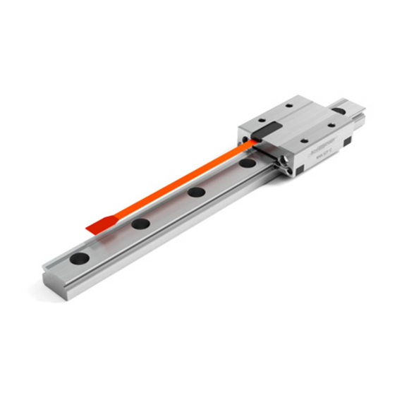
- Page 1 Sold & Serviced By: www.servo2go.com Toll Free Phone: 877-378-0240 Toll Free Fax: 877-378-0249 sales@servo2go.com sales@servo2go.com www.servo2go.com www.servo2go.com MINISCALE PLUS The unique miniature guideway with integrated measuring system and a resolution of 0.1 µm Mounting instructions 2017...
- Page 2 Sold & Serviced By: www.servo2go.com Toll Free Phone: 877-378-0240 Toll Free Fax: 877-378-0249 sales@servo2go.com sales@servo2go.com www.servo2go.com www.servo2go.com Disclaimer This publication has been compiled with great care and all information has been checked for accuracy. However, we can assume no liability for incorrect or incomplete information.
-
Page 3: Table Of Contents
Environmental Protection Handling and Storage 4.1. Transport 4.2. Protection Installation and Adjustment Guidelines for MINIRAIL and MINISCALE PLUS Serial Number on Guideway and Carriages Locating and Supporting Surfaces Methods for Aligning Guideways Preparing for Installation Installing the Guideway Tightening Torques for the Fastening Screws... - Page 4 Sold & Serviced By: www.servo2go.com Toll Free Phone: 877-378-0240 Toll Free Fax: 877-378-0249 sales@servo2go.com sales@servo2go.com www.servo2go.com www.servo2go.com...
-
Page 5: Introduction
Toll Free Phone: 877-378-0240 Toll Free Fax: 877-378-0249 sales@servo2go.com sales@servo2go.com 2.1. Scope of Application www.servo2go.com www.servo2go.com These instructions describe installation of the MINIRAIL and MINISCALE PLUS miniature profiled linear guideway systems. Configuration of MINISCALE PLUS with MINIRAIL 2.2. Supplementary Literature MINI-X Product Catalog... -
Page 6: Safety Instructions
MINIRAIL and MINISCALE PLUS must only be assembled by appropriately trained specialists who have read and understood these instructions. 3.2. Intended Use MINIRAIL and MINISCALE PLUS can only be exposed to the approved environ- mental influences (see MINI-X product catalogue, MINIRAIL and MINISCALE PLUS technical information) 3.3. -
Page 7: Handling And Storage
• Transport guideways and accessories in their original packaging • Protect guideways against impacts • Always transport MINIRAIL and MINISCALE PLUS carriages on guide rails or on the protective plastic rail 4.2. Protection The following instructions should be noted to protect against damage: •... -
Page 8: Installation And Adjustment Guidelines For Minirail And Miniscale Plus
Serial Number on Guideway and Carriages Both guideways and carriages are labelled with serial numbers. The serial number on guideways and carriages is located next to the SCHNEEBERGER logo. 5.2. Locating and Supporting Surfaces Locating and supporting surfaces on carriages and guideways are designated as follows. -
Page 9: Methods For Aligning Guideways
Sold & Serviced By: www.servo2go.com Installation and Adjustment Guidelines Toll Free Phone: 877-378-0240 Toll Free Fax: 877-378-0249 sales@servo2go.com sales@servo2go.com www.servo2go.com www.servo2go.com 5.3. Methods for Aligning Guideways Alignment of the guide rails depends on the level of accuracy needed and must be specified in the construction phase of the machine, since this is when the number of locating surfaces as well as their positions is determined. -
Page 10: Preparing For Installation
Sold & Serviced By: www.servo2go.com Installation and Adjustment Guidelines Toll Free Phone: 877-378-0240 Toll Free Fax: 877-378-0249 sales@servo2go.com sales@servo2go.com www.servo2go.com www.servo2go.com 5.4. Preparing for Installation 5.4.1 Required tools and equipment • Oil stone • Lubricant • Torque wrench • Fastening screws •... -
Page 11: Installing The Guideway
• Before installation, the guideway, machine bed, mounting plate and fastening screws must all be at room temperature. • The MINISCALE PLUS sensor is an electrostatically vulnerable component and is delivered in ESD-protective packaging. To ensure the sensor remains protected, the ESD-protective packaging should not be removed during installation of the MINISCALE PLUS guideway. - Page 12 The dimensional scale of the measuring system is located on the top side of the MINISCALE PLUS guideway. After the guideway has been fixed but before the carriage is mounted, the dimensional scale must be cleaned to ensure it can be read by the sensor.
-
Page 13: Tightening Torques For The Fastening Screws
Strength class A2-70 M1.6 5.7. Lubrication of MINISCALE PLUS If MINISCALE PLUS or MINIRAIL carriages are used on a guideway, all carriages are lubricated during manufacture (with KLÜBER Isoflex NBU15). Regarding subsequent lubrication, refer to the guidelines for MINISCALE PLUS. 5.7.1 Subsequent Lubrication Intervals for MINISCALE PLUS The subsequent lubrication interval depends on many variables, e.g. -
Page 14: Connecting The Flexible Printed Circuit Board To The Interface Module
ESD-protective packaging Conductive tape As soon as it is removed from the protective packaging, MINISCALE PLUS and the interface module of the flexible printed circuit board must be protected against electrostatic fields and discharge. As soon as MINISCALE PLUS is assembled and... - Page 15 MINISCALE PLUS should be operated. An ESD wrist strap with ground cable or crocodile clamps on the machine bed acting as such should be used as a minimum when installing MINISCALE PLUS. Provided the MINISCALE PLUS flexible printed circuit board is in the ESD-protec- tive packaging, no ESD protection or wrist strap is necessary.
- Page 16 Sold & Serviced By: www.servo2go.com Installation and Adjustment Guidelines Toll Free Phone: 877-378-0240 Toll Free Fax: 877-378-0249 sales@servo2go.com sales@servo2go.com www.servo2go.com www.servo2go.com Open ZIF connector (H) Insert the flexible printed circuit board (C) into the ZIF connector (H) of the interface module (F) without touching the gold contact points on the printed circuit board.
-
Page 17: Output Signals And Supplying Miniscale Plus And Interface Module
Sold & Serviced By: www.servo2go.com Output Signals and Supply Toll Free Phone: 877-378-0240 Toll Free Fax: 877-378-0249 sales@servo2go.com sales@servo2go.com www.servo2go.com www.servo2go.com The sensor head in the carriage sends sinusoidal output signals when the carriage is moved relative to the dimensional scale along the guide rail. These signals are interpreted in the interface module and displayed in analog (see chapter 6.2) or digital form (see chapter 6.3), depending on the type of interface module. - Page 18 Ua0 + Reference signal + 6.2.4 Function Check The green LED will light up if the MINISCALE PLUS is correctly supplied with power. Interface module without MINISCALE PLUS flexible Interface module with correctly connected printed circuit board. Both the green and red LEDs MINISCALE PLUS flexible printed circuit board.
- Page 19 6.2.5. Using the analog interface module with the USB counter 026 or 046 (for technical information, see chapter 12 in the MINI-X product catalogue). The USB counters mentioned above allow MINISCALE PLUS to be connected directly to a computer via USB. Current consumption: <...
-
Page 20: Digital Interface Module (Digital Signal Ttl)
5 µm. We therefore recommend using the SIRIUS II 2-axis SIRIUS II position indicator position indicator with the digital input option, along with the MINISCALE PLUS digital interface module. DIGITAL Interface Module (Digital Signal TTL) 6.3.1... - Page 21 Quadrature signal Reference signal 6.3.4 Function Check The green LED will light up if the MINISCALE PLUS is correctly supplied with power. Interface module without MINISCALE PLUS flexible Interface module with correctly connected printed circuit board Both the green and red LEDs MINISCALE PLUS flexible printed circuit board.
- Page 22 Using the digital interface module with the USB counter 026 or 046 (for technical information, see chapter 12 in the MINI-X product catalogue). The USB counters mentioned above allow MINISCALE PLUS to be connected directly to a computer via USB. Current consumption: <...
- Page 23 Sold & Serviced By: www.servo2go.com Output Signals and Supply Toll Free Phone: 877-378-0240 Toll Free Fax: 877-378-0249 sales@servo2go.com sales@servo2go.com www.servo2go.com www.servo2go.com • For operating the USB counter, PC software for demonstrating the functionality is available. • A DLL file is available for customers that wish to write their own software applications.
-
Page 24: Recommendations For The Customer-Supplied Cable
Sold & Serviced By: www.servo2go.com Output Signals and Supply Toll Free Phone: 877-378-0240 Toll Free Fax: 877-378-0249 sales@servo2go.com sales@servo2go.com www.servo2go.com www.servo2go.com Recommendations for the Customer-Supplied Cable The flexible printed circuit board between the sensor and the interface module can only be used statically. The bending radius of the flexible printed circuit board must not fall below 2 mm. -
Page 25: System Accuracy
If periodic deviations only occur during digitization and calculation of position, then we talk about an interpolation error. The short-wave deviation of MINISCALE PLUS is always within a range of +/- 0.6µm. Measure length [mm] Maximum positive and negative long-wave deviation (-/+ 10µm) -
Page 26: Matching The Interface Module With Carriages And Guideway
• Move the carriage slowly along the entire rail length 3 to 4 times. • Release the calibration button • Reset MINISCALE PLUS (= switch it off and on again) • Drive the carriage along the guideway and make sure the green LED lights up •... -
Page 27: Technical Principles To Aid Usage Of Miniscale Plus
Sold & Serviced By: www.servo2go.com Technical Principles to Aid Usage of MINISCALE PLUS Toll Free Phone: 877-378-0240 Toll Free Fax: 877-378-0249 sales@servo2go.com sales@servo2go.com www.servo2go.com www.servo2go.com 9.1. Interpolation For distance measuring applications, interpolation means the signal conversion of analog input signals into digital output signals with a smaller signal period. This is necessary as counter readings and/or position readings cannot be generated directly from analog signals. -
Page 28: Digital Signaling And Evaluation
Sold & Serviced By: www.servo2go.com Technical Principles to Aid Usage of MINISCALE PLUS Toll Free Phone: 877-378-0240 Toll Free Fax: 877-378-0249 sales@servo2go.com sales@servo2go.com www.servo2go.com www.servo2go.com Digital Signaling and Evaluation The digital signals, consisting of the two incremental signals A+ and B+ and the reference signal R+, are transmitted to the downstream electronics. -
Page 29: Analog Signal Frequency
Sold & Serviced By: www.servo2go.com Technical Principles to Aid Usage of MINISCALE PLUS Toll Free Phone: 877-378-0240 Toll Free Fax: 877-378-0249 sales@servo2go.com sales@servo2go.com www.servo2go.com www.servo2go.com Analog Signal Frequency In order to achieve an appropriate resolution, the analog signal must be interpolat- ed. -
Page 30: Referencing
Sold & Serviced By: www.servo2go.com Technical Principles to Aid Usage of MINISCALE PLUS Toll Free Phone: 877-378-0240 Toll Free Fax: 877-378-0249 sales@servo2go.com sales@servo2go.com www.servo2go.com www.servo2go.com Referencing Incremental measuring systems cannot determine the exact position after being switched on. For this reason, another track is added alongside the incremental track;... -
Page 31: Single-Ended Signaling
Sold & Serviced By: www.servo2go.com Technical Principles to Aid Usage of MINISCALE PLUS Toll Free Phone: 877-378-0240 Toll Free Fax: 877-378-0249 sales@servo2go.com sales@servo2go.com www.servo2go.com www.servo2go.com 9.12 Single-Ended Signaling For single-ended signaling, the voltages change relative to a reference potential (electrical ground). This is a simple and convenient way of transferring data, requiring just one wire per signal. -
Page 32: Error Description For Miniscale Plus
Flexible circuit board is damaged/bent Replace Position information MINISCALE PLUS does not corre- MINISCALE PLUS was not handled or spond to the travel installed in an ESD-compliant manner distance and is now damaged Input speed of the electronics is not... - Page 33 Sold & Serviced By: www.servo2go.com MINISCALE PLUS Error Description Toll Free Phone: 877-378-0240 Toll Free Fax: 877-378-0249 sales@servo2go.com sales@servo2go.com www.servo2go.com www.servo2go.com Error Possible Causes Solution Interpolation too low Increase interpolation Evaluation too low Repeat evaluation 4 times Resolution is not...
- Page 34 Sold & Serviced By: www.servo2go.com Toll Free Phone: 877-378-0240 Toll Free Fax: 877-378-0249 sales@servo2go.com sales@servo2go.com www.servo2go.com www.servo2go.com...
- Page 35 • GEAR RACKS • LINEAR BEARINGS and RECIRCULATING UNITS • MINERAL CASTING SCHNEEBERGER • MINISLIDE MSQscale • MINI-X MINIRAIL / MINISCALE PLUS / MINISLIDE • MONORAIL and AMS profiled linear guideways with integrated measuring system • MONORAIL and AMS application catalog •...
Need help?
Do you have a question about the MINISCALE PLUS and is the answer not in the manual?
Questions and answers