
Related Manuals for Faulhaber 22 BX4 SC Series


Summary of Contents for Faulhaber 22 BX4 SC Series
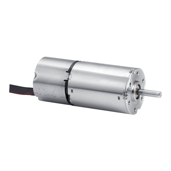
- Page 1 Technical Manual 22xx...BX4(S) SC 32xx...BX4 SC 32xx...BX4 SCDC 26xx...B SC 1525...BRC 1935...BRC 3153...BRC 2214...BXT H SC 3216...BXT H SC 4221...BXT H SC WE CREATE MOTION...
- Page 2 Dr. Fritz Faulhaber GmbH & Co. KG. This document has been prepared with care. Dr. Fritz Faulhaber GmbH & Co. KG cannot accept any liability for any errors in this document or for the consequences of such errors. Equally, no liability can be accepted for direct or consequential damages resulting from improper use of the equipment.
-
Page 3: Table Of Contents
Content About this document ....................... 5 Validity of this document ..................5 Associated documents .................... 5 Using this document ....................5 List of abbreviations ....................6 Symbols and designations ..................6 Safety ..........................7 Intended use ......................7 Safety instructions ....................7 Environmental conditions .................. - Page 4 Content 5.4.7 Minimum speed (in sensorless mode only).......... 35 5.4.8 Delayed Current Error (only error output) .......... 35 Protective functions ..................... 36 5.5.1 t current limitation................36 5.5.2 Overtemperature shutdown ..............37 Voltage output at motor ..................37 Commissioning ....................... 38 Maintenance ........................
-
Page 5: About This Document
All data in this document relate to the standard versions of the series listed above. Changes relating to customer-specific versions can be found in the corresponding data sheet. Associated documents For certain actions during commissioning and operation of FAULHABER products additional information from the following manuals is useful: Manual... -
Page 6: List Of Abbreviations
About this document List of abbreviations Abbreviation Meaning Brushless DC-motor with integrated Electronics Back-induced electromotive force Electromagnetic compatibility Electrostatic discharge Pulse Width Modulation Speed Controller SCDC Speed Controller in two-wire version Speed Control Systems Symbols and designations CAUTION! Hazards to persons. Disregard may lead to minor injuries. ... -
Page 7: Safety
Safety Safety Intended use The motors described here are designed as drives for small machines and for speed-con- trolled applications. The following points must be observed to ensure that the motors are used as intended: Handle the motors in accordance with the ESD regulations. Do not use the motors in environments where it will come into contact with water, ... -
Page 8: Environmental Conditions
Therefore the Machinery Directive does not apply to our products. The products described here are not “incomplete machines”. Therefore installation instructions are not normally issued by FAULHABER. Low Voltage Directive (2014/35/EU) The Low Voltage Directive applies for all electrical equipment with a nominal voltage of 75 to 1500 V DC and 50 to 1000 V AC. -
Page 9: Product Description
200 min (digital Hall) and 50 min (analogue Hall). Depending on the model series, FAULHABER Speed Control Systems (SCS) can be adapted to the application via the FAULHABER Motion Manager software from version 5.x or 6.x. The following can be set: Type and scaling of the set value specification ... -
Page 10: Product Information
Product description Product information … … … Speed Controller SCDC: Speed Controller, two-wire version BX4: BX4 motor family BX4S: Motor nominal voltage (12 V) Motor nominal voltage (24 V) Shaft diameter 3 mm Shaft diameter 5 mm Motor length 32 mm Motor length 42 mm Motor length 50 mm Motor length 68 mm... - Page 11 Product description BRC: Brushless DC-motor with integrated electronics Motor nominal voltage (6 V) Motor nominal voltage (9 V) Motor nominal voltage (12 V) Motor nominal voltage (15 V) Motor nominal voltage (24 V) Shaft diameter 2 mm Shaft diameter 3 mm Shaft diameter 4 mm Motor length 25 mm Motor length 35 mm...
-
Page 12: Product Variants
Product description Product variants Tab. 1: Product variants – Speed Control Systems Motor series Sensors Speed range Power supply of elec- Rated torque tronics/motor (V DC) (mNm) 2232S012BX4S SC Digital Hall 400…22 500 5…28 / 6…28 Analogue Hall 50…22 500 5…28 / 6…28 2232S024BX4S SC Digital Hall... - Page 13 Product description Motor series Sensors Speed range Power supply of elec- Rated torque tronics/motor (V DC) (mNm) Digital Hall 200…10 000 6.5…30 / 6.5…30 3216W024 BXT H SC Digital Hall 200…8 000 6.5…30 / 6.5…30 4221G024 BXT H SC The speed range depends on the maximum motor supply voltage. At metal flange.
-
Page 14: Installation
Installation Installation This description must be carefully read and observed before commissioning. Observe the environmental conditions (see chap. 2.3, p. 8). Only trained experts and instructed persons with knowledge of the following fields may install and commission the motors with integrated Speed Controller: Automation technology ... -
Page 15: Mounting The Motor
Installation 4.1.2 Mounting the motor Fig. 5: Mounting example – 22xxBX4 SC series 1. Secure the front flange of the motor to a suitable surface using fastening screws (for the screw size and torque, see Tab. 2). 2. Protect the fastening screws to prevent displacement due to the effect of heat. 3. -
Page 16: Electrical Connection
Installation 3242…BX4 SC 2610…B SC R1,5 60° Fig. 6: Comparison of round flange and quadratic flange Electrical connection 4.2.1 Notes on the electrical connection NOTICE! Electrostatic discharges to the motor connections can damage the electronic components Observe the ESD protective measures. Carry out work only at ESD-protected workstations. - Page 17 Installation Tab. 3: Permissible loads of the ribbon cables Motor series Contact spacing Permissible loads 22xx…BX4(S) SC 1.27 AWG28 Tensile load: <30 N Continuous tensile load: <17 N Bending radius with one-off installation: >1.2 mm 32xx…BX4 SC / SCDC 2.54 AWG24 Tensile load: <60 N Continuous tensile load: <20 N Bending radius with one-off installation: >1.8 mm...
-
Page 18: Electrical Connection Of Motor
Installation 4.2.2 Electrical connection of motor 4.2.2.1 EMC-compliant installation NOTICE! Signal interference may be caused if the connection cables are too long. Do not exceed a cable length of 3 m. Observe the EMC protective measures described here. EMC filter ... -
Page 19: Pin Assignment
Installation Separated suppressor diodes (D1 and D2, e.g. P6KE33A von STMicroelectronics) for U and U in case of separated supply voltages. If only one power supply is used (jumper between U and U ), one suppressor diode (D1) is sufficient. 4.2.2.3 Pin assignment NOTICE! - Page 20 Installation Tab. 6: Electrical data – motor connections on motor series 32xx BX4 SC Wire Designation Value 1 (U Electronics supply 6.5…30 V DC 2 (U Coil supply 6.5…30 V DC 3 (GND) Ground – 4 (U Input voltage = 0…10 V nsoll ➙...
- Page 21 Installation Tab. 9: Electrical data – motor connections on motor series 26xx B SC Wire Designation Value 1 (U Electronics supply 4…18 V DC 2 (U Coil supply 1.7…18 V DC 3 (GND) Ground – 4 (U Input voltage = 0…10 V nsoll ➙...
-
Page 22: Connection Examples
Installation Tab. 11: Electrical data – motor connections on motor series 2214 BXT H SC Wire Designation Value 1 (U Electronics supply 5…28 V DC 2 (U Coil supply 5…28 V DC 3 (GND) Ground – 4 (U Input voltage = 0…10 V nsoll ➙... - Page 23 Installation Normal operation (speed set value specification by U nsoll 0 – 10 V 5 kW nsoll 2,2 kW – 12 V Fig. 9: Normal operation (speed set value specification by U nsoll With the switch open, the connected motor rotates anticlockwise at a controlled speed; ...
-
Page 24: Description Of Functions
Description of functions Description of functions Operating modes 5.1.1 Speed-controlled operation The actual value for speed used for speed control can be determined by means of the sig- nals used for commutation. The configurations described below differ with regard to the used commutation type. -
Page 25: Bl Motors With Analogue Hall Sensors
Description of functions The following basic parameters are preset in this configuration: Designation Explanation Set value specification Analogue Digital output Frequency output Operating mode Speed-controlled 2-quadrant operation with brake func- The speed is reduced by short-circuiting the motor tion Speed filter Active The following settings can be made by the user: Designation... - Page 26 Description of functions The resolution of the analogue Hall sensors means that stable speed control is possible from approx. 50 min In this configuration, the commutation signal is determined via the analogue Hall sensors. The position information from the analogue Hall sensors is used for commutation of the motor and for speed determination.
-
Page 27: Bl Motors Without Hall Sensors (Brc Motors)
Description of functions 5.1.1.3 BL motors without Hall sensors (BRC motors) Digital output Electronics supply Motor supply 22 kΩ Protection function: Overtemperature 3 Phase Phase A MOSFET Power Phase B BL-Motor output Setpoint input block Phase C PI velocity nsoll soll stage commutator... -
Page 28: Operation As Voltage Controller
Description of functions The following settings can be made by the user: Designation Explanation Set value specification The following set value specifications can be set (see chap. 5.2, p. 28): Fixed speed mode Speed set value specification via analogue signal ... -
Page 29: Analogue Set Value Specification
Description of functions 5.2.2 Analogue set value specification [min undefined soll area setMax nsoll 10 V Fig. 15: Set value determination for speed controller The analogue input can process voltages from 0 V to 10 V. An analogue set value specification of 10 V corresponds to the value specified in the ... -
Page 30: Pwm Set Value Specification
Description of functions 5.2.3 PWM set value specification Digital output Electronics supply Motor supply 22 kΩ Protection function: Overtemperature 3 Phase Phase A MOSFET Power Phase B BL-Motor Setpoint input output block Phase C PI velocity nsoll soll stage commutator controller PWM signal Evaluation... -
Page 31: Configuration Of The Digital Output
Description of functions Configuration of the digital output The digital output can be configured for the following tasks: Fault output When current limitation is activated, the output switches to high level. The delay between activation of current limitation and setting of the output can be adjusted. When current limitation is deactivated, the output switches to low level. -
Page 32: Parameter Settings
Description of functions Parameter settings The parameters listed below can be used to adjust the Speed Controller to the respective application. A number of the parameters listed here are only effective in certain configura- tions or with certain settings. 5.4.1 Current limitation values For I t current limitation, it is possible to set the peak current (I... -
Page 33: Fixed Speed
Depending on the cooling factor, operating point and ambient temperature, the current limitation parameter can be adapted using the FAULHABER Motion Manager. The specified values apply in the case of 22 °C ambient temperature and the nominal voltage for motor and electronics. -
Page 34: Maximum Speed
Description of functions 5.4.4 Maximum speed If a speed set value is specified by means of an analogue voltage or PWM signal, it is then possible to adjust the speed value which is to be set at 10 V DC and at a duty cycle of 100%. In this way, the maximum speed is adapted to the application. -
Page 35: Controller Parameters
Description of functions 5.4.5 Controller parameters The controller parameters are preset at the factory. They can be adapted for special applica- tions. The following requirements with respect to the control system can be identified: Control rigidity Uniformity of the speed within one revolution ... -
Page 36: Protective Functions
Description of functions Protective functions 5.5.1 t current limitation t current limitation protects the motor against overheating. A thermal current model which calculates the motor temperature is created for this purpose. The motor current is influenced depending on the calculated temperature. The following values are relevant for t current limitation: ... -
Page 37: Overtemperature Shutdown
Description of functions If the calculated model temperature reaches a critical value (T ), the current controller crit comes into effect and limits the motor current to the continuous current (I cont Area II: As in this area the calculated model temperature reaches the critical temperature (T ... -
Page 38: Commissioning
Commissioning Commissioning CAUTION! Hazards due to hot surfaces. Depending on the load and ambient temperature, the motor can overheat. Allow the motor to cool down after operation. Be sure to wear protective gloves when touching the motor shortly after operation. CAUTION! Risk of injury caused by protruding, rotating or moving parts of the driven mechanical units. - Page 39 Commissioning 6. Reduce the controller gain until the system is stable again. 7. Repeat steps 2 to 6 for the proportional/integral component (VI). The motor is ready for operation. 2nd edition, 31-03-2020 7000.05061, 2nd edition, 31-03-20207000.05061...
-
Page 40: Maintenance
Maintenance Maintenance Maintenance tasks The motor is generally maintenance-free. Where the device is mounted in a cabinet, depending on the deposition of dust the air filter should be regularly checked and cleaned if necessary. Troubleshooting If unexpected malfunctions occur during operation according to the intended use, please contact your support partner. -
Page 41: Accessories
Accessories Accessories The following accessories are available: Article Article no. Contact adapter 6501.00112 Programming adapter USB 6501.00096 Details on configuration can be found in the Motion Manager manual (see chap. 1.2, p. 5). Details on the connection sequence can be found in the product data sheet of the pro- gramming adapter. -
Page 42: Warranty
Warranty Warranty Products of the company Dr. Fritz Faulhaber GmbH & Co. KG are produced using the most modern production methods and are subject to strict quality inspections. All sales and deliv- eries are performed exclusively on the basis of our General Conditions of Sale and Delivery which can be viewed on the FAULHABER home page www.faulhaber.com/gtc and down-... - Page 43 DR. FRITZ FAULHABER GMBH & CO. KG Antriebssysteme Daimlerstraße 23 / 25 71101 Schönaich • Germany Tel. +49(0)7031/638-0 Fax +49(0)7031/638-100 info@faulhaber.de www.faulhaber.com 7000.05061, 2nd edition, 31-03-2020 © Dr. Fritz Faulhaber GmbH & Co. KG...
Need help?
Do you have a question about the 22 BX4 SC Series and is the answer not in the manual?
Questions and answers