
Related Manuals for Faulhaber 3564K024BC series


Summary of Contents for Faulhaber 3564K024BC series
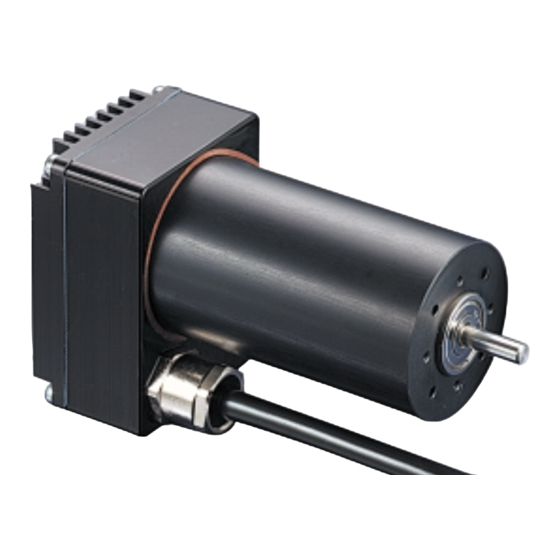
- Page 1 Sine Wave Commutated Brushless DC-Servomotor with Integrated Motion Controller Series 3564 K 024 BC Instruction Manual...
-
Page 2: Table Of Contents
Table of Contents General Information Data Sheet Cables and Connections Analog Velocity Control Simple Possibilities to Set Command Velocity with a Potentiometer 10 RS-232 Port and the ASCII Commands Default Configuration of the RS-232 Port The ASCII Commands Saving Configurations Changing the Baud Rate Setting the Node Address Configuring the Velocity Control... - Page 3 Additional Modes Stepper Motor Mode Gearing Mode Position Control with a Voltage at the Analog Input Using an External Encoder to Measure Actual Position Voltage Regulator Mode Handling Errors and the Error Output Show Deviation from Command Speed as Error Delayed Activation of the Error Display The Error Output as a Digital Output Pulse Output...
-
Page 4: General Information
The 3564K024B C integrates an electronically For users of Windows 95/98/NT we provide commutated servomotor, an high resolution the “FAULHABER Motion Manager”, a fully encoder and a programmable motion controller, functional configurations and operations manager based on a powerful 16-Bit Microcontroller, in with on line graphic performance analysis. -
Page 5: Data Sheet
Data Sheet Motor 3564K 024B C Supply Voltage Output Power 2max Efficiency No Load Speed 9000 No Load Current 0,38 Maximum Torque Torque Constant 20,2 mNm/A Current Constant 0,05 A/mNm Mechanical Time Constant Rotor Inertia Angular Acceleration rad/s Thermal Resistance 2,5 / 6,3 Thermal Time Constant 23 / 1175... - Page 6 Data Sheet Electronics 3564K 024B C Supply Voltage 12 ... 28 V DC Peak Current Input No. 1 Input Resistance kΩ Nominal Velocity Voltage Range ± 10 Slope of the Curve 1000 rpm/V Nominal Velocity Digital PWM Signal low 0...0,5 / high 4...30 Frequency Range 100 ...
-
Page 7: Cables And Connections
Cables and Connections Lead Function blue pink +24 V brown Analog Input white Fault Output grey Analog GND yellow RS-232 RXD green RS-232 TXD Diagram 1: Connections with the adapter board I Input for the external encoder in Encoder Power Supply Requirements Mode (Analog input to ground: Channel The power supply should deliver at least 5 A. - Page 8 Cables and Connections Fault Output The fault output is activated as a result of the following situations: The system is outfitted with a fault output I Dynamic current limiting active through which system errors are signalled. I Low voltage (by voltage under 10 V) Fault Output Characteristics: I Switch to ground (open collector) I Overvoltage protection active...
-
Page 9: Analog Velocity Control
Analog Velocity Control On delivery the 3564K024B C In this operating mode the is configured as a velocity RS-232 is not required but can control. The command speed be used to alter configurations. is given as a voltage at the More on the topic of “Altering analog input. -
Page 10: Simple Possibilities To Set Command Velocity With A Potentiometer
Analog Velocity Control Simple Possibilities to Set Command Velocity with a Potentiometer Diagram 3 Diagram 4 Diagram 3 shows the simplest possibility, Some Comments about the Input Circuit but note the following: The input circuit at the analog input is layed I The command velocity depends on out as a differential amplifier. -
Page 11: Rs-232 Port And The Ascii Commands
RS-232 Port and the ASCII Commands The RS-232 port allows the 3564K024B C to be Building blocks of the ASCII Commands connected to a personal computer as well as 1.) Node Address (option...just necessary various digital controllers, like for example a in a network) SPS or an IPC. -
Page 12: Saving Configurations
RS-232 Port and the ASCII Commands Saving Configurations Parameters and configurations can be saved in an on board EEPROM chip. That means that saved programs and configura- tions are not lost in case of a loss of power. Upon connec- tion to the supply voltage the motor runs under the setup saved in the EEPROM. -
Page 13: Setting The Node Address
RS-232 Port and the ASCII Commands Setting the Node Address Command Function Description Example NODEADR *) Define Node Defines the node address NODEADR5 With the assistance of the Address from (0 bis 255) RS-232 Multiplexer Board it GNODEADR Get Node Calls up node address GNODEADR ➔... -
Page 14: Configuring The Velocity Control
Configuring the Velocity Control Upon delivery the motor is set Sources for Velocity up as a velocity controller. The Command Function Description Example input signal is a voltage at the SOR *) Source For Sources for the Velocity SOR 1 analog input, for example, Velocity SOR 0: Command velocity at the... - Page 15 Configuring the Velocity Control Setting the Minimal Analog Voltage Command Function Description Example MAV *) Minimum Analog Sets the minimum MAV500 Voltage analog voltage GMAV Get Minimum Calls up the minimum analog GMAV ➔ Analog Voltage voltage over the RS-232 port. Example: MAV100 [return] ➔100 mV is the necessary minimum starting voltage.
- Page 16 Configuring the Velocity Control Setting the Direction of Rotation: Command Function Description Example ADL *) Analog Direction Armature rotates left Left with positive voltage at the analog input ADR *) Analog Direction Armature rotates right with Right positive voltage at the analog input Default Setting: ADR ...
- Page 17 Configuring the Velocity Control Setting an Acceleration: Command Function Description Example AC *) Load Command Loads a new value for AC100 Acceleration acceleration Arguement in Rev/s2 Get Acceleration Calls up current ➔ 1000 accelaration value Default Setting: 30000 Rev/s This acceleration value makes soft acceleration and braking in Velocity Control Mode possible.
-
Page 18: Fine Tuning The Digital Filter
Configuring the Velocity Control Fine Tuning the Digital Filter The digital filter parameters can be adjusted to improve the dynamic performance. These parameters should be carefully chosen to fit the application because they have a great influence on performance. Command Function Description Example POR *) -
Page 19: Position Control
Position Control The following Command Sequence is necessary to switch from Speed Control Mode (factory setting) to Positioning Mode: ➔ Switches to RS-232 Communication in Speed Control Mode SOR0 [enter] ➔ Load Relative Position 0 [enter] ➔ Switches to Positioning Mode [enter] Positioning commands: Command Function... -
Page 20: Standard Positioning Sequences
Position Control Standard Positioning Sequences Combined Motion Profiles 1.) Enter the acceleration and the maximum Through well chosen values (Maximum Velocity, velocity (rpm) Acceleration, end Position) entered during a positioning sequence one can create complex AC50 [enter] ➔ Sets acceleration to 50 Rev/s motion profiles. -
Page 21: Evaluating The Homing Points And Limiter Switch
Evaluating the Homing Points and Limiter Switch The following are the available Allocation : inputs and signals: Name of Limit Switch Input Binary Number Answer and Input Address Number Symbol I Analog Input Analog Input I Fault Pin Fault-Pin (programmed as input) I Zero Index of Hall Sensor A binary “1”... -
Page 22: Direct Programming With The Ha, Hl And Hn Commands
Evaluating the Homing Points and Limiter Switch Setting the Edge and Polarity Example circuit diagrams for the Fault Pin Limit Switch and the Analog Input are pictured in Diagram 7 and Diagram 10. The trigger edge and polarity must be chosen depending on how the limit switch is connected. -
Page 23: Programmable Homing Sequence
Evaluating the Homing Points and Limiter Switch Programmable Homing Configuring the Homing Sequence Sequence 1. Set the special homing sequence actions with the HA, HL, HN commands. The programmable homing sequence has the following 2. Save the special actions in the intermediate memory with the advantages: CAHOSEQ (Capture Homing Sequence) command I When programmed the... -
Page 24: Hard Blocking Function
Evaluating the Homing Points and Limiter Switch Hard Blocking Function Command Function Description Example HB*) Hard Blocking Activates or deactivates To ensure that the motor does hard blocking at a given not run past the limit switch, it limit switch. is possible to program the limit 1: activate 0: deactivate... -
Page 25: Additional Modes
Additional Modes Additional “special modes” Command Function Description Example CONTMOD*) Continuous Switches motor back to CONTMOD were developed in order to Mode Continuous Mode from fulfill the requirements of as any of the additional modes. many different applications as GMOD Get Mode Calls up current mode: GMOD... - Page 26 Additional Modes Advantages over a conventional stepper motor: Command Function Description Example STEPMOD*) Stepper Switches to STEPMOD I The step count per revolution is programma- Motor Mode Stepper Motor ble and has very high resolution Mode STW *) Load Step Sends the step STW1 I The step width is programmable...
-
Page 27: Gearing Mode
Additional Modes Gearing Mode In Gearing Mode it is possible to connect an external encoder to provide the command position value. Diagram 10: Gearing Mode with a reference point at the Fault Pin The reduction ratio is calculated just as in Stepper Motor Mode. Command Function Description... -
Page 28: Position Control With A Voltage At The Analog Input
Additional Modes Position Control with a Command Function Description Example APCMOD*) Analog Position Switches to analog APCMOD Voltage at the Analog Control Mode positioning mode Input LL*) Load Position Loads position limit: LL10000 In this mode the command Range Limits Provides the maximum position at the maximum position value can be regula-... -
Page 29: Using An External Encoder To Measure Actual Position
Additional Modes The direction of rotation is set with the ADR and With the following commands it is possible to ADL commands. position the motor inside one revolution with a voltage ranging from 0 - 10 V even after the ADR ➔... - Page 30 Additional Modes Diagram 12: External encoder a position and speed signal source The maximum position, Command Function Description Example ENCMOD*) Encoder Switches to encoder mode. ENCMOD which is set with the Mode Position is registered by an LL command, can range external encoder.
-
Page 31: Voltage Regulator Mode
Additional Modes Voltage Regulator Mode Command Function Description Example VOLTMOD*) Set Voltage Mode Activates voltage VOLTMOD The motor can be configured regulator mode with the VOLTMOD command to serve as a voltage regulator. In this mode it is possible to use an external controller. The motor voltage is propor- The controller on the motor than functions as a power amplifier. -
Page 32: Handling Errors And The Error Output
Handling Errors and the Error Output The standard error functions Show Deviation from Command Speed as Error and the way that these errors In certain applications a greater degree of deviation from the can be rectified are described given command speed is unacceptable. Therefore the unit in detail in the chapter should be programmed to react by displaying an error. -
Page 33: Delayed Activation Of The Error Display
Handling Errors and the Error Output Delayed Activation of the Error Display The delay time before displaying an error, during which the current limiting, over voltage protection or the deviation error are active can be programmed with the “Delayed Current Error” function. -
Page 34: The Error Output As A Digital Output
Handling Errors and the Error Output The Error Output as a Digital Output Aside from the ability to function as a limit switch input (REFIN) and a direction of rotation input (DIRIN), the error output can also function as a digital output. This makes it possible, for example, to control a valve directly or to send a signal as a reaction to a certain event. -
Page 35: Pulse Output
Handling Errors and the Error Output Pulse Output Pulses from the Hall Sensor are processed and are then sent out at the fault output. Properties of the pulse output: I Maximum Pulse Frequency: 2000 Pulses per second I At speeds in excess of the maximum pulses per second the maximum pulse frequency will be transmitted I The programmed number of pulses will be reached exactly. -
Page 36: Saving And Running Programs
(Windows-Editor, Word) and Note: The “FAULHABER Motion Manager” program provides sent to the drive with a termi- a comfortable way to program sequences and configure nal program. The programs are the motor. -
Page 37: Controlling A Program Sequence
Saving and Running Programs Controlling a Program Sequence The following are added commands for controlling a program sequence while it is running. These commands are only available while the program sequence is running. When the following commands are used the current program is interrupted until a certain criteria is fulfilled: ... -
Page 38: More About Commands And Functions
Saving and Running Programs Continuation: Additional Commands Command Function Description Example RETI Return Error Jumps back from the error subroutine to the main RETI Interrupt program. Important: The interrupted command will not repeat upon jumping back to the main program even if it hadn’t fully been carried out before the interrupt. - Page 39 Saving and Running Programs About the ERI Command Example: At first after entering the ERI command nothing La100000 happens. The command only takes effect after SP5000 an error occurs. The program then jumps to AC50 the given address. In this way a continuation NV1000 of the program even after an error occurs is possible.
-
Page 40: Technical Information
Technical Information Commutation with a Sine Wave Operating Mode of the Current Controller When the power is turned on to the motor, Sine wave commutation means that the rotating the current controller sends the value for peak magnetic field is always ideally positioned to the current as the command current value. -
Page 41: Overtemperature Protection
Technical Information Analog command current About Measuring the Temperature of the Winding I The SOR3 command can be used to switch to the analog command current input. The temperature of the motor is measured on The current limit is proportional to the the casing and compared to the measured voltage at the analog input. -
Page 42: Appendix
Appendix Electromagnetic Compatibility (EMC) The System fulfills the following requirements (norms) during operation at nominal values: The sine wave commutated servomotor with EMC emissions according to the range defined by integrated motion controller (3564K024B C) VDE 0839 part 81-2 (EN50081-2) was tested and measured for EMC according to the european guideline (89/336/EWG). -
Page 43: Starter-Kit, Adapter And The Rs-232 Multiplexer Board
Multiplexer Board The Adapter Board and the Zero-Modem Cable: To make integration in new systems easier, Faulhaber can provide an adapter board with screw clips and a 9 pole SUB-D connector to connect directly to a PC, a SPS, or an IPC. - Page 44 Appendix The 3564 Starter-Kit: The following components make up the Starter-Kit: I 3564K024B C I Starter-Kit board I A zero-modem cable Diagram 15: Starter Kit board After connecting the supply voltage the motor is ready for experimentation. The speed can be regulated with the potentio- meter included on the board.
- Page 45 It is possible to chain up to 255 motors. It is also possible to chain the 3564K024B C with other Faulhaber motion controllers, for example, the MCDC2805 and the MCBL2805. It is important to remember that when controlling multiple...
-
Page 46: The Ascii Command Set
Appendix I In the following list, examples of possible The ASCII Command Set answers to request commands are indicated I All commands that are marked with a *) with an arrow. will be saved with the EEPSAV command. I Answering Commands, whitch take effect only after a certain criteria has been met, are marked by the word “asynch”. - Page 47 Appendix Commands for Motion Control Command Function Description Example M *) Initiate Motion Activates positioning mode and starts positioning Load Absolute Loads new absolute position. LA100000 Position Arguement: 1000 is one rotation. Load Relative Position Loads a new relative position LR5000 V *) Select Velocity Mode...
- Page 48 Appendix Commands For Evaluating Homing Points and Limit Switches Command Function Description Example Define Home With no Arguement: Sets the actual position to 0 Position With Arguement: Sets actual position to the given value HP *) Hard Polarity Sets the trigger edge and the polarity for the limiter switches: 1**): rising edge and high level 0**): falling edge and low level...
- Page 49 Appendix Continuation: Commands For Evaluating Homing Points and Limit Switches Command Function Description Example GAHS ➔ 33300 GAHS Get Actual 5 numbers with values between 0 and 3 are sent Homing Status to the host over the RS-232. They indicate the status of the homing switches.
- Page 50 Appendix Commands for Additional Modes Command Function Description Example CONTMOD *) Continuous Mode Switches from the present further mode CONTMOD back to continuous operating mode. (Hall Sensor gives actual position. Communication over the RS-232) STEPMOD *) Steppermotor Mode Switches to stepper motor mode. STEPMOD STW *) Load Step Width...
- Page 51 Appendix Commands for Configuration of the Error Functions and Error Output Command Function Description Example DIRIN *) Direction Input Programs the fault output as a direction of DIRIN rotation input. (The limiter switch is also thereby activated) REFIN *) Reference Input Programs the fault pin as a limit switch REFIN ERROUT *)
- Page 52 Appendix More Request Commands Command Function Description Example POS ➔ 500000 Get Actual Position Calls up the actual position GN ➔ 4000 Get N Calls up the actual speed GCL ➔ 2800 Get Current Limit Calls up the actual current limit value GRC ➔...
- Page 53 Appendix Continuation: More Request Commands Command Function Description Example GSCS ➔ 00000001 GSCS Get Special Calls up configuration at the host RS-232 (8 Bits) Configuration Set From left to right: Bit 0: 1 ... Power On Homing Sequence is active 0 ...
-
Page 54: Example Configurations And Programs
Appendix Example Configurations and Programs Velocity Control: Command value received at the RS-232 port. The following examples are programmed from Goals: the basis of the factory settings. I Velocity control at the RS-232 port. Velocity Control: Command value received as a PWM signal I Two active limiter switches (high level active) at the analog input. - Page 55 Appendix Position Control Stepper Motor Mode Goals: Goals: I Position control I Operation as a stepper motor I Limit acceleration to 300 Rev/s I Step Width: 3 I Reference point at falling edge I Step Number per Revolution: 557 I Active Power On Homing Sequence with I Controller Parameters: Proportional 25 and integral 8 the fault pin as reference input...
- Page 56 Appendix Program Sequence: Configuration: Calling up Various Positioning Routines ➔ Switches to receive command SOR0 at the RS-232 speed at the RS-232 This program makes it possible to call up various ➔ Motion stop programs at the RS-232 port. ➔ Switches to position control I Homing: The motor first runs to a limiter (no motion) switch then to the Hall index zero.
- Page 57 Appendix ➔ Jump-in address for sequence 2 Commentary: ➔ Set peak current to 500 mA... I The homing sequence is called up by sending LPC500 (continuous current ≤ peak the JMP2 command from the RS-232. current) The other routines are called up in a similar manner.
- Page 58 Appendix ➔ Loads homing speed (backward) HOSP-200 ➔ Rising edge will be registered at the limit switch ➔ Run to position 0 if high logic ➔ Program will activate after ENPROG level at input 2 power on ➔ Jump to the beginning JMP1 ➔...
-
Page 59: Factory Configuration
Appendix Factory Configuration The commands in the factory configuration are as follows: ➔ Deavctivate homing sequence CAHOSEQ ➔ Drive is active ➔ Power on homing sequence is POHOSEQ0 ➔ Command speed 0 deactivated ➔ Homing speed is 100 with ➔ Source for velocity is the HOSP100 SOR1 direction of rotation right... - Page 60 14881 Evergreen Avenue Clearwater · FL 33762-3008 · USA Phone: +1 (727) 572-0131 Fax: +1 (727) 573-5918 Toll-Free: (800) 807-9166 Email: info@micromo.com www.micromo.com From Software Version 305010A and upwards © DR. FRITZ FAULHABER GMBH & CO. KG MA05003, english, 1. Edition, 29.04.02...
Need help?
Do you have a question about the 3564K024BC series and is the answer not in the manual?
Questions and answers