Table of Contents
Advertisement
Quick Links
Instructions
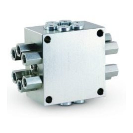
USP Valve
Uniblock Series Progressive Valve for oil and grease lubrication.
5076 psi (35 MPa, 350 bar) Maximum Working Pressure
Important Safety Instructions
Read all warnings and instructions in this
manual. Save these instructions.
Models
For all models:
•
Discharge per outlet = 0.012 in
No. of
Model No.
Outlets
24E406
6
24E407
8
24E408
10
24E409
12
24E410
14
24E411
16
3
Inlet Thread
1/8 NPT
1/8 NPT
1/8 NPT
1/8 NPT
1/8 NPT
1/8 NPT
3A0860J
EN
ti13743
Advertisement
Table of Contents

Related Manuals for Graco Uniblock Series


Summary of Contents for Graco Uniblock Series
- Page 1 Instructions USP Valve 3A0860J Uniblock Series Progressive Valve for oil and grease lubrication. 5076 psi (35 MPa, 350 bar) Maximum Working Pressure Important Safety Instructions Read all warnings and instructions in this manual. Save these instructions. Models For all models: •...
- Page 2 Warnings Warnings The following warnings are for the setup, use, grounding, maintenance, and repair of this equipment. The exclama- tion point symbol alerts you to a general warning and the hazard symbols refer to procedure-specific risks. When these symbols appear in the body of this manual, refer back to these Warnings. Product-specific hazard symbols and warnings not covered in this section may appear throughout the body of this manual where applicable.
-
Page 3: Installation
Installation Installation Option 1 The USP Valve should be ready to install in your sys- tem. It has been factory-tested and should not require 1. Remove the outlet adapter from block. any additional modification. 2. Remove face seal (a) from outlet adapter (b) (F As long as lubricant is supplied under pressure, the valve will continue to operate . -
Page 4: Pressure Relief Procedure
Installation 2. Plug outlet using Graco doubling plug accessory Before machine operation is resumed, following mainte- part number 24F467 (F . 3). nance or repair procedures, manual system air purging is required. Purging Air from Pump to USP Valve Lines... - Page 5 Installation Purging Air After Adding or Replacing a USP Valve Module ti14065 Steps 1- 7, refer to F . 6. 1. Install the new USP valve assembly. 2. Connect the tubing or hoses to the appropriate valve or lubrication point(s) 3.
-
Page 6: Cleaning Valves
Graco distributor to verify age. Higher pressure is limited, isolated and signaled compatibility with centralized lubricating systems. - Page 7 Parts Parts FN Part No. Description VALVE, 4 piston honed, models 24E406, 24E407 VALVE, 6 piston honed, models 24E408, 24E409 VALVE, 8 piston honed, models 24E410, 24E411 24E757 PLUG, w/o ring, models 24E406, 24E407 PLUG, w/o ring, models 24E408, 24E409 PLUG, w/o ring, models 24E410, 24E411 24E857 KIT, checked outlet adapter, NPSF...
-
Page 8: Technical Data
Technical Data Technical Data Wetted Parts Steel, Fluorocarbon Maximum Pressure 5076 psi (35 MPa, 350 bar) Maximum Operating Temperature Fluorocarbon seals 350°F (177°C) Lubricant Oil or grease up to NLGI #2 Output Volume 0.012 in Inlet Threads 1/8 - 27 NPT Outlet Adapter Threads 1/8 - 27 NPSF Maximum Cycle Rate with Prox Switch... - Page 9 Technical Data Outlet Pattern Numbering NOTE: • Port combinations do not continue across factory plugged outlets. Factory plugged ports are included on 6, 10 and 14 outlet USP Valve models. On the following diagrams the factory plugged outlets are represented as blacked ports.
-
Page 10: Graco Standard Warranty
With the exception of any special, extended, or limited warranty published by Graco, Graco will, for a period of twelve months from the date of sale, repair or replace any part of the equipment determined by Graco to be defective.
Need help?
Do you have a question about the Uniblock Series and is the answer not in the manual?
Questions and answers